
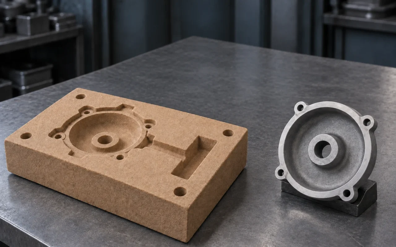
What aluminum sand casting involves
An aluminum housing with internal passages must meet requirements for its outer shape, channels, mounting interfaces and sealing. If the design is still evolving, the manufacturing plan must also accommodate revisions. The flexibility of sand mold and core production often makes sand casting a candidate for such projects.
Aluminum sand casting pours molten aluminum alloy into a cavity formed by a sand mold. After solidification, the mold and cores are removed to obtain a raw casting. Suitability depends on geometry, quantity and quality requirements; machining and inspection are still needed to turn the casting into an accepted part.
Why consider sand casting for small batches large parts and complex cavities
The Aluminum Association’s overview of casting processes lists sand casting among the main aluminum casting routes and identifies smaller quantities, complex structures and large castings as cases worth evaluating economically. Tooling, cores and production conditions help explain these characteristics.
Conventional molding uses a pattern to form the cavity and a core box to produce cores. Tooling can be chosen to suit the task; directly printing sand components can reduce some pattern and core-box preparation. When development parts change frequently, compare the tooling affected by each revision, rather than considering only the initial quotation.
Sand cores form internal cavities and are removed after casting. They offer a manufacturing option for curved passages, complex cavities and some shapes from which a rigid core would be difficult to withdraw. Feasibility also depends on core support, positioning, venting and sand removal. Permanent molds can also use sand cores, so complex internal geometry must be assessed as part of a complete process plan.
For large parts, feasibility depends jointly on molding space, melting capacity, lifting, pouring and cleaning capabilities. Being able to design a large sand mold and a foundry being able to produce the casting reliably are conditions that need separate confirmation.
There is no universal quantity threshold for a small batch. With existing tooling, simple geometry and suitable conventional production arrangements, the current route may be more economical. Digital coremaking is worth assessing when several designs are needed in small quantities and revisions mainly affect complex cores.
Start with the alloy grade and service requirements
“Cast aluminum” identifies only a broad material category. Pure aluminum and aluminum alloys have different compositions, and casting alloys differ in their material and delivery requirements. Procurement documents should specify the grade, applicable standard and condition.
Before selecting a material, establish the loads, pressure or leak-tightness requirements, exposure to corrosive media, and any subsequent welding, heat treatment or machining. If a project specifies A356 and a particular heat-treatment condition, for example, retain those details in inquiry, production and acceptance documents. This illustrates document completeness; the actual grade follows the functional requirements.
The Aluminum Association’s guide to standards for sand and permanent mold castings organizes engineering dimensional requirements separately from metallurgical properties. Dimensions, tolerances and machining allowances form one set of questions; alloy composition, condition and properties form another.
Material evidence should also identify what it represents. A chemical analysis relates to a material batch, specimen properties reflect the agreed test specimen, and inspections of critical areas address the part itself. For demanding castings, design and quality teams should establish at the inquiry stage what evidence is required and who will supply it.
Three areas of control for aluminum alloys
Melt quality
Oxides form on the surface of molten aluminum, and flow during melting, transfer and pouring can carry them into the melt. Dissolved hydrogen behaves differently: its solubility decreases during solidification and it may contribute to porosity. Melt cleanliness and gas content therefore need separate assessment.
Filtration principally addresses relevant inclusions; degassing manages dissolved gas. Material and transfer practices affect initial contamination and the risk of subsequent gas pickup. The AFS introduction to molten aluminum cleanliness treats inclusions, hydrogen and melt treatment as related but distinct issues. Treatment methods and results should be validated for the material and the foundry’s process.
Mold filling
The gating system determines the path of metal into the cavity. Thin-wall extremities and longer passages require assessment of filling and temperature loss; around cores, erosion, gas entrainment and inclusions also need consideration. Binders, coatings and venting in molds and cores influence conditions after metal contacts the mold.
Filling and solidification should be validated together. AFS descriptions of aluminum casting research projects indicate that relationships between oxide films, porosity and mechanical results under different filling conditions require further study. Smoother flow alone therefore does not establish better final properties.
Solidification and feeding
Metal changes volume as it solidifies. If a local region needs liquid metal but its supply path has already solidified, shrinkage cavities or shrinkage porosity may form. Thick sections, thickness transitions, riser locations and cooling conditions should be reviewed together. Foseco’s explanation of casting defects distinguishes solidification feeding from hydrogen-related porosity mechanisms.
Core venting, melt degassing and riser feeding address different stages. When a void is found, first investigate its location, shape and process records before deciding which operation to examine. For a fuller distinction, see investigating gas porosity, shrinkage cavities and shrinkage porosity.
From process preparation to inspection
- Process preparation: Confirm the material, finished-part requirements and raw-casting revision. Plan parting, machining allowances, cores, gating and feeding. Identify critical functional surfaces at this stage.
- Mold and core production and assembly: Make the molds and cores, checking dimensions, integrity, location and venting. Printed sand components also need powder removal and any required post-processing, with confirmation that internal passages can be cleaned.
- Melting treatment and pouring: Manage material batches, return metal, melt treatment and transfer according to a validated process. Check that the actual mold condition matches the process documents.
- Solidification cooling and cleaning: Follow the planned cooling, shakeout, core removal and gating-and-riser removal procedures. For complex cavities, verify residual sand and cleaning effectiveness; a clean exterior does not establish that the interior is clean.
- Heat treatment and machining: Complete the treatment required by the material and delivery specification. Machine mounting surfaces, holes and mating features, retaining the relationship between casting batches and machining revisions.
- Inspection and first-article acceptance: Check dimensions, material and internal quality in the agreed areas using specified methods and acceptance criteria, then confirm functional requirements.
These steps interact. Access for core-removal tools can affect the design, for example, while machining a critical sealing surface affects when inspection should occur. Assess the material system alongside foundry sand, binders and used-sand circulation, and consult the complete sand casting production process for the full production sequence.
Aluminum parts worth evaluating
| Part category | Requirements to assess | Acceptance considerations |
|---|---|---|
| Pump bodies and fluid housings | Internal passages, complex cores and machining allowances | Sealing, passage cleanliness and critical dimensions |
| Equipment and transmission housings | Large structures, mounting interfaces and multiple revisions | Mating dimensions, distortion and material properties |
| Powertrain development parts | Changes to water and oil passages and prototype needs | Material condition, passages and test objectives |
| Functional parts with cooling passages | Passage geometry and core manufacture | Flow, leakage, cleanliness and thermal performance |
The table helps screen candidate parts. Actual production plans follow each product’s service requirements; two parts both called “housings” may need different materials, wall thicknesses and inspections.
Consider a hypothetical aluminum housing with an internal cavity: the external interfaces are stable, but the internal passages still need testing. Conventional coremaking can support repeat production once the design matures. Printed cores with a conventional outer mold allow assessment of whether changes can be concentrated internally; printing the complete mold allows assessment of preparation when both internal and external contours change.
Compare core positioning, assembly, sand removal and casting compatibility before calculating tooling and sand-component production costs. The example assumes no route is inherently better; the decision depends on the actual extent of revisions and foundry conditions.
Matching defects to inspection
Internal voids in aluminum castings can involve gas, solidification feeding or several interacting factors. The AFS course introduction on aluminum casting defects discusses gas porosity and shrinkage porosity separately. Analysis requires locations, shapes and process records, rather than a photograph alone.
| Issue | Focus of investigation |
|---|---|
| Oxides or other inclusions | Melt and transfer records, inclusion locations and relevant internal inspection |
| Gas porosity | Melt gas content, gas entrainment, core gas evolution and venting |
| Shrinkage cavities or shrinkage porosity | Hot spots, solidification sequence and effective feeding paths |
| Cold shuts or misruns | Incomplete areas or seam locations, filling paths and temperature loss |
| Sand-related surface defects | Mold integrity, coatings, erosion and cleaning condition |
| Distortion | Critical datums, wall-thickness distribution and cooling or post-processing records |
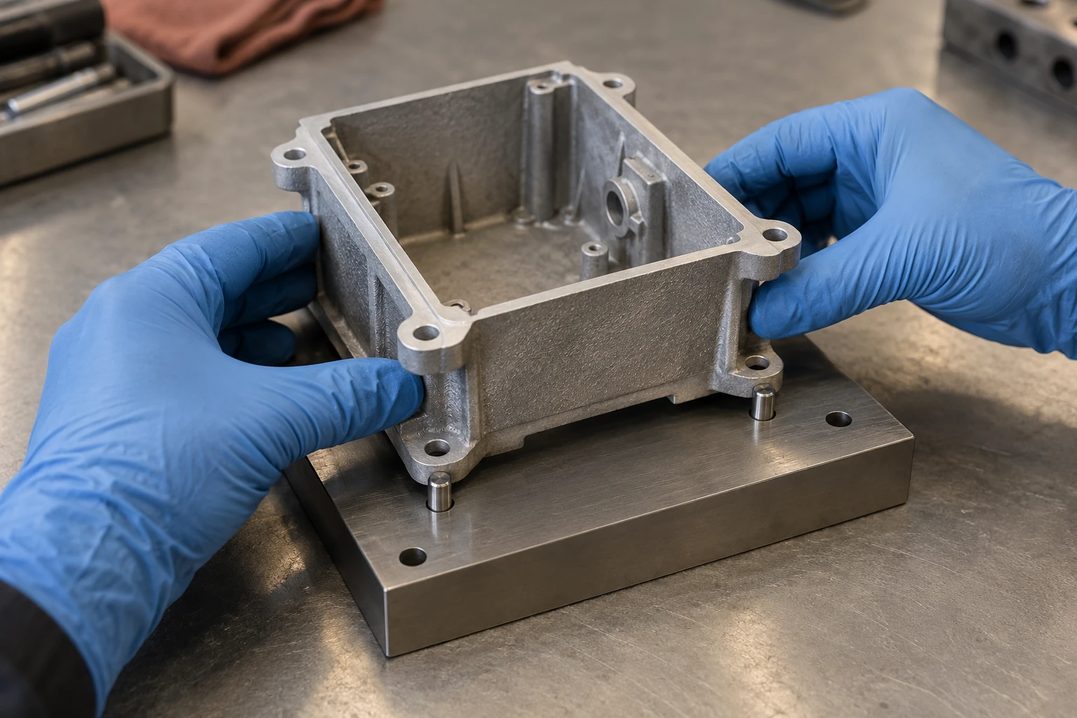
Work backward from service requirements to define the inspection plan. Dimensional measurement checks geometry; penetrant inspection addresses surface-breaking defects in suitable materials, with matching surface conditions and procedures. Magnaflux’s explanation of liquid penetrant inspection explains this scope.
Radiography or CT can be used for agreed internal-quality inspections. Nikon’s industrial CT inspection information lists assessment of porosity, shrinkage and foreign material among its uses. Detectability still depends on the part, equipment and inspection conditions. Pressure or leak testing addresses sealing, while material and mechanical testing addresses the corresponding property requirements; each method answers a different question.
Specify the inspection stage for critical machined surfaces. Machining may expose voids previously below the surface, so sealing surfaces should be accepted in the agreed condition. Stating “requirement, area, method and stage” in an inquiry helps establish whether quotations cover the same quality work.
When to compare permanent molds or high-pressure die casting
A sand mold is expendable, so molding, assembly, shakeout and cleaning belong in the production cycle. As-cast surface and dimensional capability depend on sand, molding, coatings and pouring conditions; critical mating surfaces often need machining. Include these recurring operations alongside tooling investment in the cost assessment.
First distinguish two dimensions of process selection: sand and permanent molds describe mold material, while gravity, low pressure and high pressure describe filling methods. The table compares three common routes to frame review questions; the supplier must confirm capability for the actual part.
| Common route | Tooling and production characteristics | Conditions to compare |
|---|---|---|
| Sand casting | A suitable mold is needed for each casting; conventional molding or printed sand components can be used | Quantity, revisions, cavities, cleaning and machining |
| Gravity permanent mold casting | Reusable metal tooling; demolding and mold thermal condition need management | Design stability, core withdrawal, repeat production and tooling investment |
| High-pressure die casting | Metal tooling with pressurized filling and suitable equipment | Sustained volumes, wall thickness and filling, tooling and equipment conditions |
Permanent molds can also use sand cores, as described in Foseco’s explanation of low-pressure casting. Low-pressure and high-pressure equipment, filling and process conditions should be assessed separately; similar names do not imply identical capabilities.
When the design is stable and demand continues, compare the production arrangements enabled by reusable tooling. For multiple small batches, complex cavities or frequent revisions, calculate tooling changes separately. Further volume and economic analysis is available in choosing between sand casting and high-pressure die casting.
These considerations suggest assessing cavity design and tooling revisions together for aluminum sand casting, then including cleaning, heat treatment, machining and acceptance costs. Quotations for the same part are comparable only when they cover the same delivery scope.
Using printed sand molds in aluminum part development
One approach prints only the complex cores while retaining conventional outer molds. It suits assessment of projects where changes are concentrated inside and existing outer tooling remains usable, but core-to-mold location, assembly and material compatibility need confirmation.
Another approach prints the complete set of molds and cores. This can reduce the preparation of corresponding patterns and core boxes and offer an option when internal and external geometry change together. ExOne’s overview of sand 3D printing explains the basic ability to produce sand components from CAD and revise designs digitally.
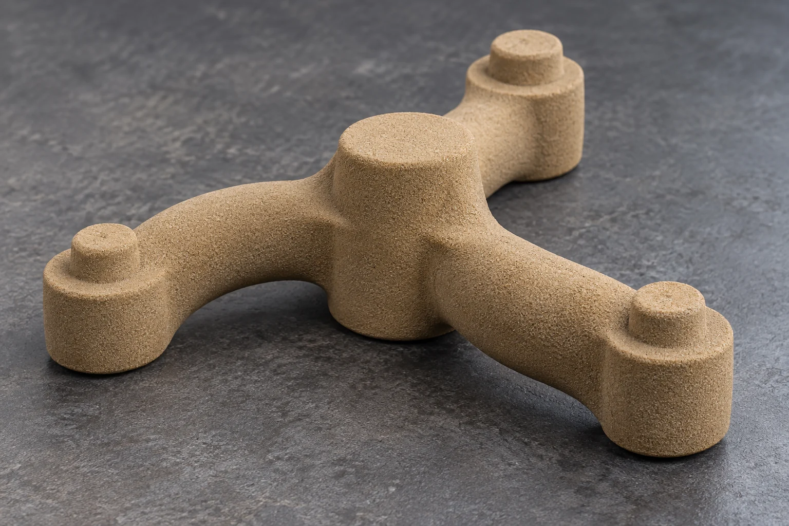
Both approaches require validation of powder removal, sand-component strength, coatings, gas evolution and actual casting results. Printed dimensions are only one link in the chain: solidification, cleaning and post-processing also affect casting dimensions. Machining critical mating surfaces remains a decision based on final requirements.
First-article lead time should include data preparation, sand-component production, pouring, post-processing and acceptance. For small batches with existing tooling, retain the conventional route as a comparison.
The Cprint 3D SJ-1200 sand 3D printer produces sand molds and cores; metal parts are subsequently made through the casting process. To assess a project, provide the target part, material and delivery condition, quantity, existing tooling and critical acceptance requirements. These help determine whether to discuss complete-mold printing or selected core production.
Frequently asked questions
Can all aluminum alloys use the same sand casting process
Alloy grade, delivery condition, geometry and functional requirements affect the process. Specify the material clearly and confirm production conditions for the actual project.
Do all aluminum sand castings need heat treatment
Heat treatment depends on the material and delivery requirements. When required, specify the condition, acceptance basis and subsequent machining and reinspection.
Can sand casting produce thin-wall aluminum parts
It can be assessed, considering wall thickness, flow distance, geometry and filling conditions. Validate the feasible range for the actual plan rather than applying a universal minimum wall thickness.
Are all voids in aluminum sand castings gas porosity
Voids can involve gas, inadequate feeding or both. Analyze defect shape, location, internal inspection and production records together before choosing corrective action.
Is 3D printed sand tooling always better for small batches
Existing tooling, geometry and production arrangements affect economics. Compare total input from data preparation to accepted-part delivery, distinguishing complex-core printing from printing the entire mold.