
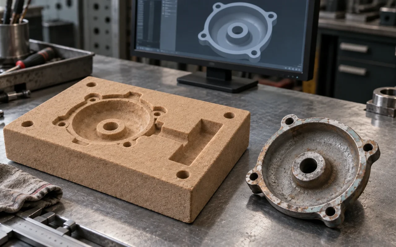
The equipment is still running, but its spare part has been discontinued. All you have is a component that is worn, cracked or partly missing. The obvious solution is to scan it into a 3D model and manufacture a replacement from that model.
The difficulty is that a scan captures the part as it is today, which may differ from how it was meant to leave the factory. It records wear and distortion, and may also capture weld repairs or earlier mistakes. Copying it without interpretation can reproduce the old problems in a new component.
Recreating a discontinued part means recovering confirmed functions, dimensional relationships, materials and manufacturing conditions. 3D scanning provides geometric evidence, reverse engineering interprets and reconstructs it, and casting is one possible route to a physical part.
Confirm that the project is feasible before scanning
Start by establishing the component’s origin, intended use and the work you are authorized to carry out, rather than selecting scan accuracy. The equipment owner, design rights holder, maintenance party and manufacturer need to clarify permission to use the information and make the part. Responsible personnel or specialists should resolve uncertainty; discontinuation by the original manufacturer does not automatically permit unrestricted copying.
Next, establish the risks. An ordinary cover cannot follow the same approval and acceptance process as a high-speed rotating, pressure-containing or safety-critical component. Such functions require a team able to take responsibility for design confirmation, material selection and validation.
Then define the objective: restore the original function, accommodate new assembly conditions or improve performance as well? Do not combine these tasks in a model with no change history. A project that changes function involves more than geometric reproduction.
Also assess whether casting remains appropriate. The original component may have been forged, welded or machined. Access to a sand printer does not make casting the right solution for every missing spare part.
One old component is only one source of evidence
Alongside the old part, collect mating components, assembly photographs, maintenance records, historical inspection data, equipment manuals and any available material information. Comparing several examples of the same model can help distinguish common design features from damage to an individual part.
For example, an apparently oval hole may be the result of prolonged wear rather than an intentional design. Its counterpart on another component, the mating shaft dimensions and assembly datums may provide further evidence.
Similarly, a local protrusion could be an original manufacturing feature or a later weld deposit. Scan software alone cannot decide whether to retain it. The original operating orientation, contact areas and failure locations also matter when interpreting the geometry.
Before measuring, photograph the component with scale and orientation information, and record visible wear, cracks, missing areas and repairs. This preserves a route back to the original evidence after reconstruction, rather than leaving only a mesh that has been repeatedly smoothed.
Why scan data is not a manufacturing drawing
Common scanning workflows produce point clouds or meshes that represent sampled surfaces. Manufacturing also requires datums, critical dimensions, tolerances, surface requirements and material information. A scan file generally does not supply all of these automatically.
Siemens’ introduction to reverse engineering also distinguishes scan output from a manufacturable model. Engineers must process and interpret the data in light of its intended use; completing a scan does not complete the engineering definition.
For visible surfaces, account for reflections, occlusion, scan alignment and positioning. Internal passages that ordinary optical scanning cannot see require other evidence or measurement methods. Closing a mesh in software does not mean the missing areas were actually measured.
Under suitable conditions, industrial CT can help capture internal geometry. Nikon’s inspection service description lists internal passages, wall thickness and reverse engineering applications, but component size, material and equipment conditions affect usable results. Before selecting a method, identify the feature to recover and the confidence required in its measurement.
Different dimensions need not all be measured by the same instrument. Regular bores, mating positions, freeform surfaces and internal cavities can use appropriate methods, with the results aligned to common datums. The aim is a dependable engineering basis, rather than the most impressive scan display.

Recover design intent by separating measurements from assumptions
When rebuilding the model, distinguish three kinds of information: features directly measured under reliable conditions; reconstructed features supported by multiple sources of evidence; and areas that still depend on assumptions.
Keep these categories explicit in the records. If a critical fit, minimum wall thickness or load-bearing feature rests only on inference, state the additional validation required. Do not silently turn it into a released production dimension.
Worn surfaces deserve particular care. Smoothing a damaged edge into an attractive surface is a geometric operation. Restoring its function requires attention to original contacts, clearances, loads and motion. A closer match to the scan does not necessarily mean a more correct design.
Avoid overfitting as well. Reproducing every pit and irregularity in CAD may preserve casting texture or damage rather than useful design features. Build the model around functional and manufacturing needs, while retaining comparison with the original data.
A practical review sheet can list the evidence, measurement method, reconstruction, remaining uncertainty and approver for each critical feature. If an assembly problem emerges later, the team can identify the judgment that needs review.
Material cannot be identified by color and weight alone
Appearance and simple physical observations offer clues, but cannot replace material confirmation. Components of the same discontinued model may have different material versions, heat treatments, surface treatments or repair histories.
Combine historical information with appropriate material testing to establish what must be confirmed about chemistry, microstructure or properties. Materials and quality personnel should decide the project-specific requirements from the intended use. A single portable test result is not proof of every relevant property.
If the original material is difficult to source, treat substitution as a formal design change. Easier casting does not demonstrate equivalent performance in the original operating conditions. Similar grades do not automatically justify reusing the same heat treatment and machining plans.
Likewise, years of successful service by the original part do not prove that a geometrically similar new casting will perform the same way. Manufacturing processes, internal condition and actual operating conditions can alter the outcome. Establish who gives final approval for material selection and service requirements.
The finished-part model still needs a casting design
The reconstructed finished-part model defines the final component. Casting also requires a production-ready blank and process plan, including appropriate dimensional compensation, machining allowances, parting, cores, pouring and feeding.
Machined holes and sealing surfaces need not reach their final condition in the as-cast blank. Establishing machining datums and fixturing first can reduce the risk of producing a casting that is difficult to machine.
For internal features, reassess how cores will be made, located and removed. Directly printed sand molds or cores are options worth evaluating for complex parts without original tooling. Their print data should still come from an approved process model, rather than an uninterpreted scan mesh.
ORNL’s research abstract on additive manufacturing for casting compares directly printed single-use sand molds with printed reusable patterns. It shows that additive manufacturing can enter casting through more than one route. Benefits reported for a particular study cannot be transferred to a new project without calculation.
Other choices include retaining usable old tooling, repairing it, making new patterns or core boxes, and combining conventional outer molds with printed cores. Compare them against quantity, geometry and future replenishment frequency. Missing drawings do not automatically require an entirely printed mold system.
Use five essentials of sand mold design to review the process model point by point.

A public case illustrates the need for staged validation
A NIST Manufacturing Extension Partnership case describes the reconstruction of an impeller for Renegade Marine Jet Drive. The team used scanning and CAD to recover the design, then made a resin prototype to check its shape. Subsequent wax-making trials for investment casting encountered uneven shrinkage and dimensional problems. The source also states that the company continued evaluating manufacturers. See the original NIST case study.
The case documents scanning, model recovery and exploration of manufacturing routes. It does not establish stable production casting or directly demonstrate the effectiveness of printed sand molds. It illustrates real differences between engineering stages: progress with a digital model and prototype does not remove the possibility of new difficulties in final metal production.
A similar staged approach is useful for discontinued parts. Confirm geometry and assembly first, review materials and the manufacturing route next, then complete first-article inspection and the specified functional validation. Clear acceptance criteria at each stage explain what the next investment is intended to resolve.
Agree on first-article validation before manufacturing
Do not wait for the casting to arrive before deciding how to validate it. Before placing an order, specify the dimensions to measure, the machining condition at measurement, the required material evidence and whether internal or functional testing is needed.
For complex housings, define at least the critical assembly relationships and cavity requirements. Rotating parts also require relevant specialist validation. The team responsible for the product must set the test conditions; this article’s general workflow is not an executable test specification.
Separate validation into several areas:
- Geometry: datums, fits, interfaces, critical wall thicknesses and internal contours.
- Materials: agreed composition, delivery condition and supporting property evidence.
- Manufacturing quality: required checks for defects and the condition after cleaning and machining.
- Function: approved tests based on the actual application.
- Documentation: matching revisions for models, drawings, process plans and inspection results.
If the first article fails, determine whether the cause lies in design reconstruction, casting, machining or interpretation of the inspection before deciding what to change. Altering a model merely to accommodate one casting deviation can embed a process problem as a new design error.
Also state what a successful first article demonstrates. Does it show that one sample of a particular revision meets requirements, or has the process qualification needed for ongoing production been completed? Keep those claims separate in the delivery documents.

A digital spare-parts library needs more than an STL file
If the project leaves only a printable mesh, the next order may still lack a specified material, machining method or acceptance criteria. Useful digital spare-part records should support the next controlled manufacturing run.
Retain, at minimum, original measurement data, reconstructed CAD, finished-part drawings, material and condition requirements, casting blank and process information, machining datums, an inspection plan, first-article results and approval records. Manage access and traceability for subcontractor data according to the agreements.
Do not overwrite original data with the final model. The data is evidence; the model contains engineering judgments. If a recovered dimension later proves problematic, it must remain possible to examine what was measured and why it was changed.
Manufacturing records should also distinguish design revisions from process revisions. A change to pouring while the design stays the same must be traceable. A change to a mating dimension with an unchanged process requires a fresh review of its effects.
Saving the records does not make future production a one-click operation. Suppliers, materials, equipment and quality requirements can change. Before replenishment, check whether current manufacturing conditions still fall within the original validation scope.
How should you assess printed sand molds for small quantities?
When tooling is missing, geometry is complex and quantities are limited, printed sand molds may reduce investment in new patterns or core boxes. Total costs still include reverse measurement, engineering reconstruction, process design, casting, machining and inspection.
A printing quotation is therefore not a quotation for delivered spare parts, and material weight alone cannot determine total cost. For critical spares, confirming the design and validation results may matter more than the mold itself.
Ask suppliers to separate one-time engineering costs, per-batch preparation and per-part manufacturing costs, then compare current demand and possible future replenishment. If original tooling is sound and materials and processes are established, retaining the existing route may be more appropriate.
The relevant role of the Cprint 3D SJ-1200 is producing sand molds and cores. At the outset, provide shareable physical samples or model data, missing information, intended use, batch quantity and acceptance requirements. First establish whether the upstream data and casting conditions are sufficient.
For legacy engine parts, engine cooling passages and printed sand cores can help explain the relationship between internal cavities and sand cores. For the complete manufacturing chain, refer to the sand casting process guide.
Frequently asked questions
Can reverse engineering start with only one worn component?
An initial assessment is possible, but the information recoverable from it is limited. Critical worn areas may require mating parts, historical records or other measurements. Do not assume that one sample directly reveals every original dimension.
Does higher scan accuracy always produce a more accurate replacement?
No. Measurement, datums, design reconstruction, casting and machining all affect the result. A dense mesh cannot automatically correct mistaken design judgments or manufacturing conditions.
Can ordinary optical scanning capture all internal passages?
It generally cannot directly capture hidden internal surfaces. Depending on the geometry, consider other inspection methods, measurements or available records, and identify areas that were not directly measured.
If the first article fits, is it ready for long-term service?
Fit alone is insufficient. Confirm materials, manufacturing quality and required functional validation for the application. Safety-critical components especially need specialist approval.
Does a completed digital model eliminate the need for engineers?
No. Digital records can reduce repeated preparation, but every manufacturing run still requires checks of revisions, supply conditions and quality requirements. They preserve a controlled engineering basis; they do not automatically waive validation.