
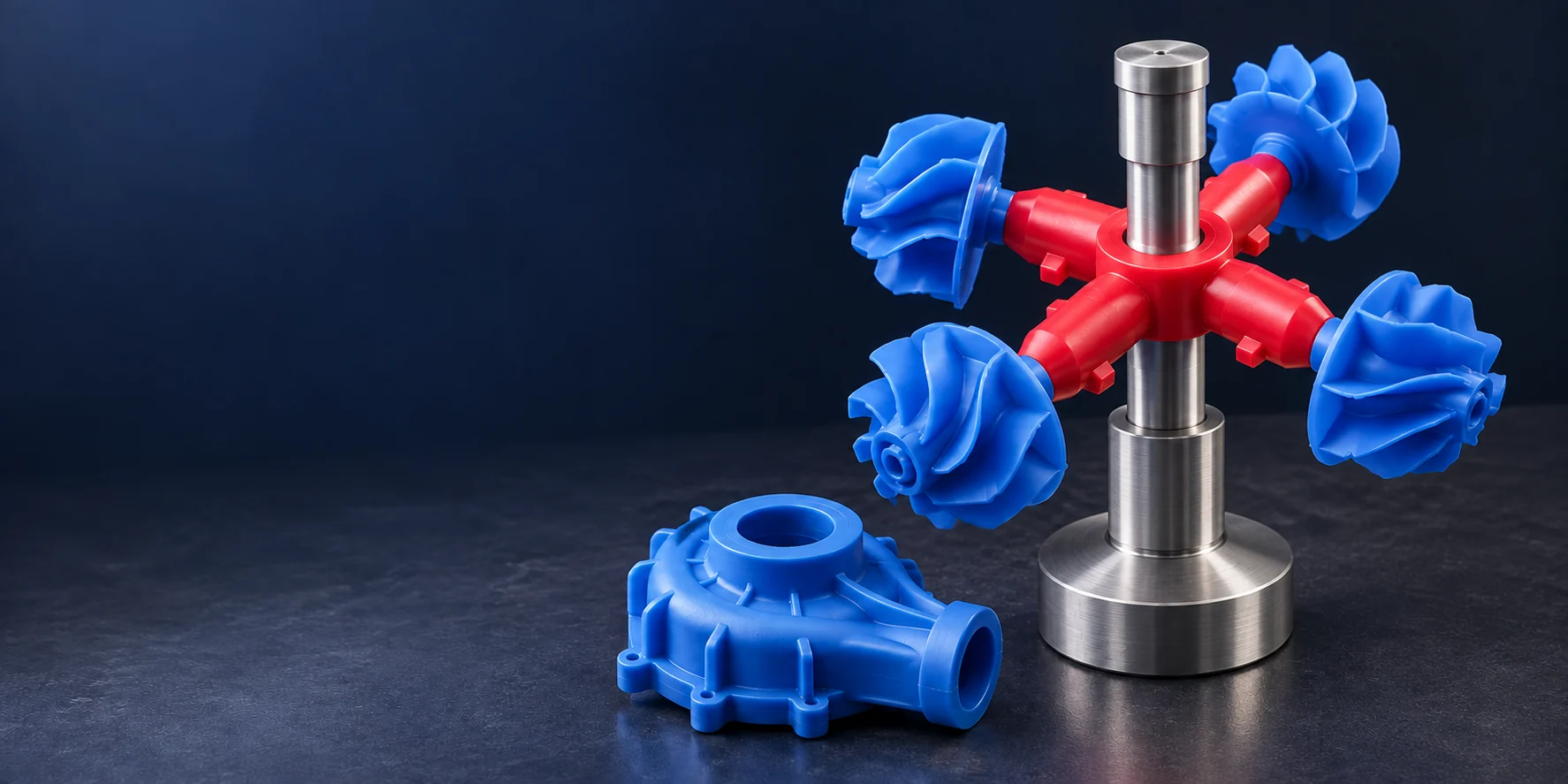
3D Printing for Investment and Precision Casting
Produce complex industrial wax patterns directly from approved CAD data for precision investment casting. Cprint 3D supports detailed geometries, mixed-part builds, repeat orders, and production-scale pattern manufacturing while allowing the printed wax patterns to move into established tree assembly, shell building, burnout, metal pouring, and finishing workflows.
PRODUCTION CAPABILITY
Industrial Wax Pattern Production at Scale
Use a digital wax pattern workflow to manage multiple part types, repeat orders, and ongoing investment-casting production without preparing dedicated pattern tooling for every new or revised design.
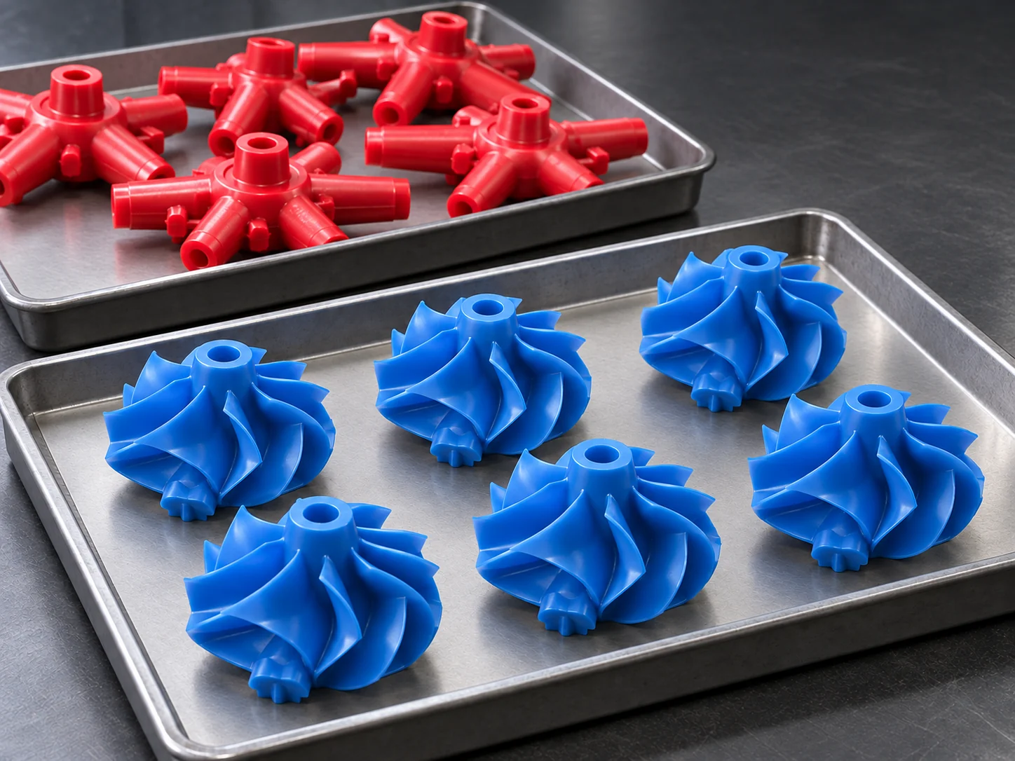
Produce More Industrial Wax Patterns in Every Build
Arrange multiple approved wax patterns across the available build area to support scheduled casting work and production demand. Part orientation, spacing, support, and cleaning access are planned around each geometry so the build is organized for usable output—not just maximum theoretical part count.
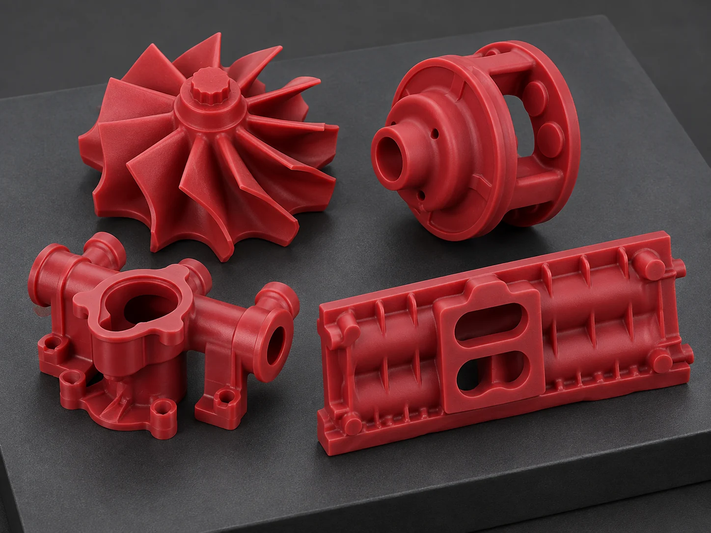
Combine Different Parts and Repeat Orders
Different approved part numbers, sizes, and order quantities can be arranged in the same build when their geometry and process requirements are compatible. Controlled digital files also make it easier to return to repeat orders without preparing dedicated wax tooling for every variation.
CASTING APPLICATIONS
Precision-Cast Components for Digital Wax Patterns
Digital wax patterns support complex industrial components that benefit from fine detail, controlled geometry, and repeatable production.
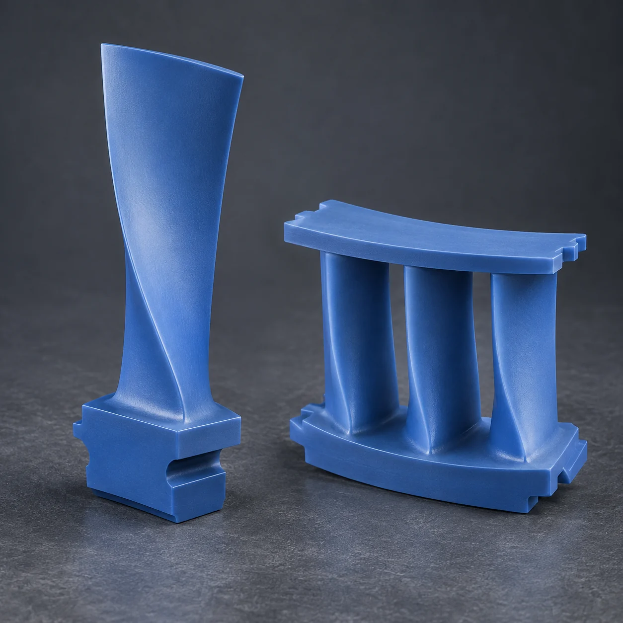
Turbine Airfoils and Nozzle Components
Produce thin airfoil profiles, defined leading and trailing edges, platforms, and repeated blade geometry for subsequent precision casting.
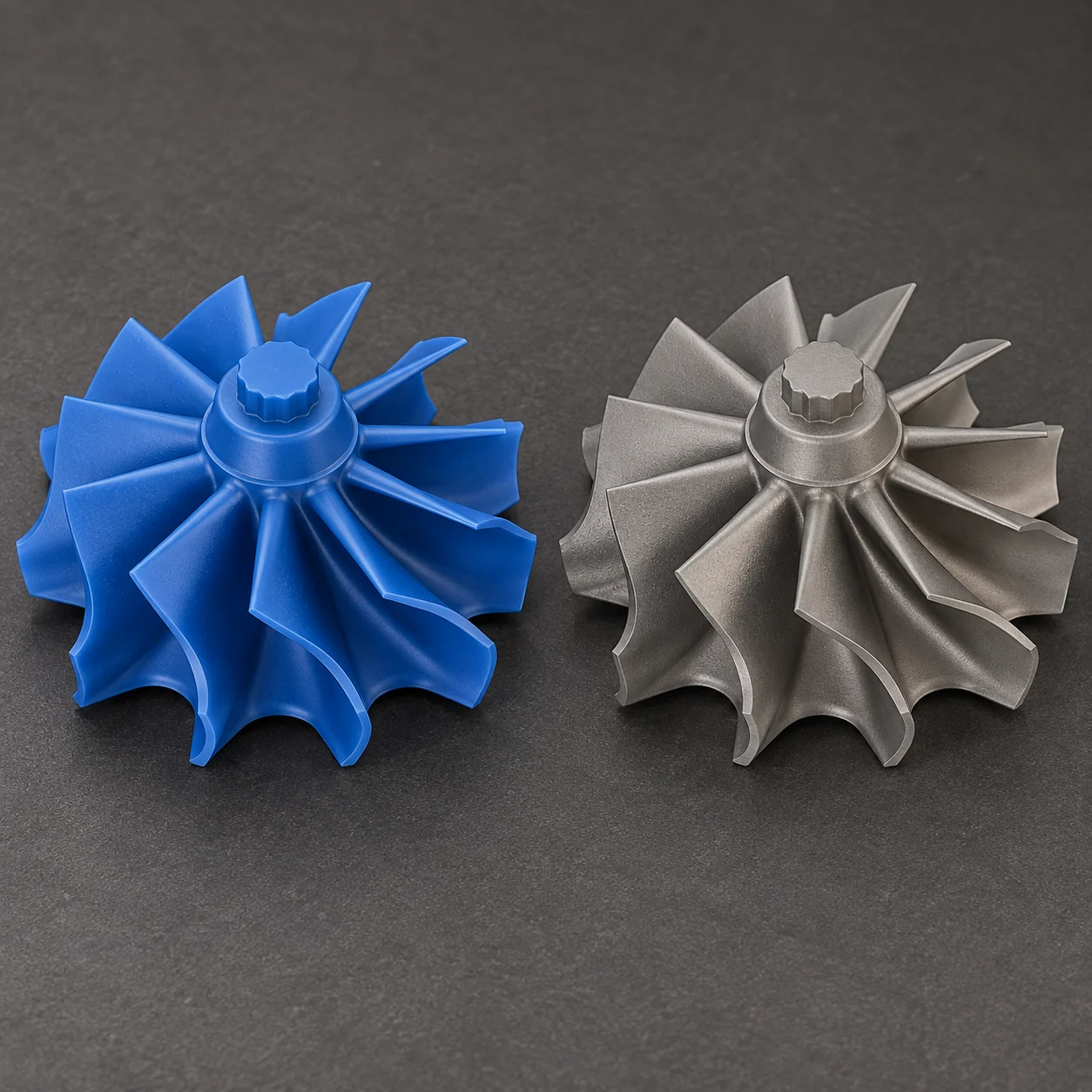
Precision Impellers and Rotors
Create closely spaced blades, curved flow surfaces, and integrated hubs while supporting design variants and repeat production.
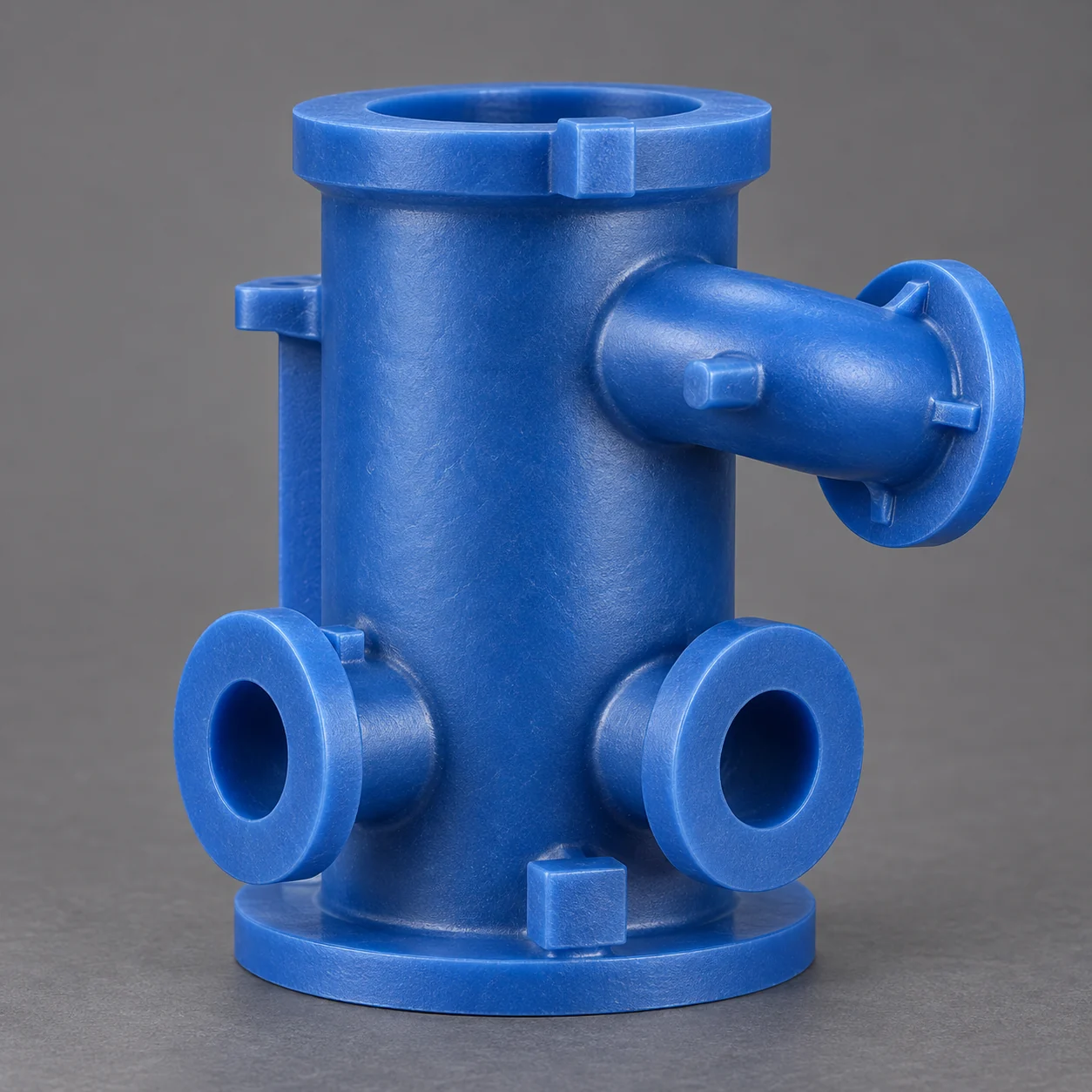
Pump, Valve and Flow-Control Parts
Produce compact fluid-handling components with flanges, intersecting features, sealing interfaces, and other precision geometry.
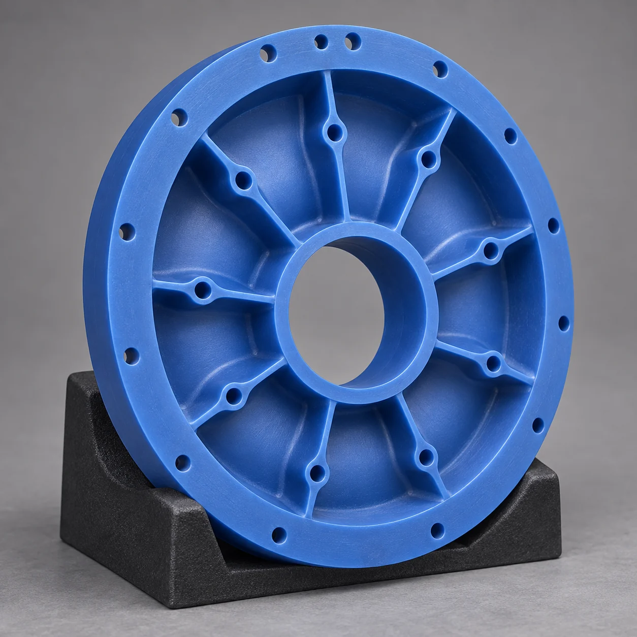
Thin-Walled Mechanical Components
Build lightweight brackets, compact housings, and integrated parts with ribs, bosses, mounting features, and controlled wall sections.
Application suitability depends on part size, alloy, wall thickness, internal features, ceramic-core strategy, and foundry process requirements.
DIGITAL CASTING WORKFLOW
A Direct Digital Path to Investment Casting
Approved CAD data becomes a physical wax pattern first—not a finished metal part. The pattern then continues through established investment-casting operations, allowing digital pattern production to fit into existing foundry workflows.
DIGITAL WAX PATTERN PRODUCTION
Review CAD and Casting Requirements
Confirm part geometry, build orientation, support strategy, and downstream casting requirements.
Prepare and Print Wax Patterns
Arrange approved parts and produce detailed wax patterns from controlled digital files.
Clean and Inspect
Remove support material where required, clean the patterns, and verify their condition before foundry handling.
ESTABLISHED FOUNDRY OPERATIONS
Assemble the Pattern Tree
Attach approved patterns to the gating system according to the foundry’s established tree design.
Build the Shell and Remove Wax
Form the ceramic shell, remove the wax, and prepare the mold for metal pouring.
Pour, Finish and Inspect
Pour the selected alloy, remove the shell and gates, finish the surfaces, and inspect the final casting.
The printed wax pattern is a casting intermediate—not the finished metal component.
WHY CPRINT 3D
Why Use Cprint 3D for Investment Casting Wax Patterns
Cprint 3D combines a 100% paraffin-wax build material, wax-based support, and a controlled digital workflow to produce complex industrial patterns for investment casting.
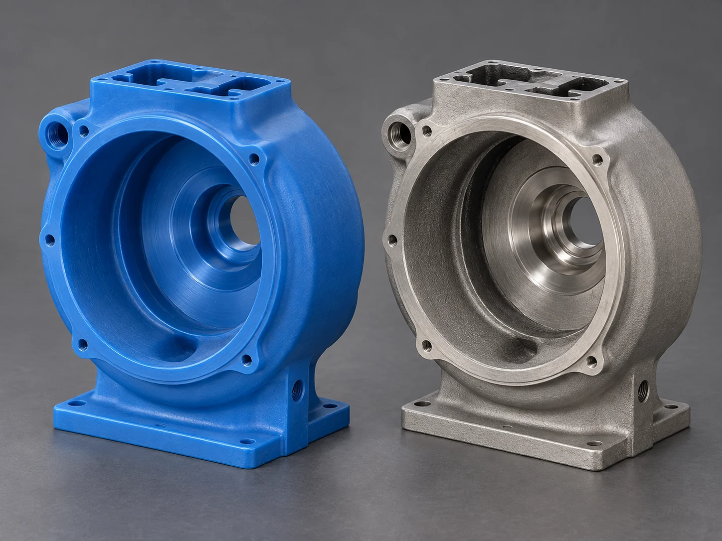
100% Wax Build Material
Produce patterns with a paraffin-based wax material rather than castable photopolymer resin, supporting evaluation within established lost-wax casting processes.
Complex Geometry with Fine Detail
Reproduce thin sections, curved blades, ribs, bosses, and closely spaced features across a wide range of precision-cast components.
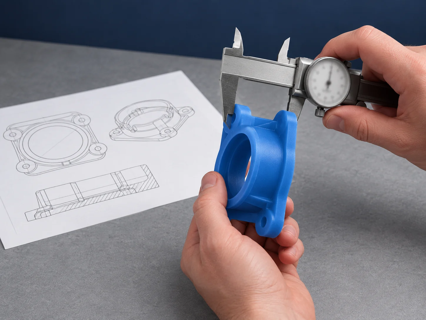
Wax-Based Support for Delicate Features
White wax-based support stabilizes lower surfaces, fine features, slots, and undercuts during printing, then follows the qualified Cprint 3D cleaning procedure for removal.
Controlled Digital Production
Work from approved digital files to manage design revisions, mixed builds, and repeat orders without creating new pattern tooling for every variation.
WAX PATTERN GUIDES
Investment Casting Wax Pattern Guides
Explore practical guidance on complex industrial patterns, post-processing, and the role of wax 3D printing across investment-casting applications.
 Ways to Make Wax Patterns for Casting
Compare hand carving, CNC milling, wax injection and direct wax printing. Understand the inputs, tooling, revisions and inspection needed to choose or combine production…
Read the Article
 What Is Wax 3D Printing? From Digital Models to Casting Patterns
Learn how wax 3D printing turns digital geometry into casting patterns, how build and support wax work together, and what happens between file preparation,…
Read the Article
 How to Schedule Small-Batch Jewelry Production Across Multiple Designs
Organize small jewelry orders from design approval and mixed wax builds to urgent jobs, style identification and casting handoffs, with three example order types…
Read the Article
HAVE A QUESTION?
Frequently Asked Questions About 3D Printing for Investment Casting
Find practical answers about printed wax patterns, production use, foundry integration, and project evaluation.
Prepared CAD data is used to produce physical wax patterns. After support removal, cleaning, and inspection, the patterns proceed through tree assembly, ceramic shell building, wax removal, shell firing, metal pouring, finishing, and inspection.
It is a sacrificial replica of the intended metal component, prepared with the required casting allowances and assembly interfaces. It forms the geometry inside the ceramic shell and is removed before metal pouring.
Yes. Approved digital files can be reused for repeat orders, and multiple compatible parts can be arranged in one build. Practical output depends on part size, nesting, printing and cleaning capacity, inspection requirements, and the foundry schedule.
Common candidates include turbine airfoils, guide vanes, nozzle components, precision impellers, rotors, compact pump and valve parts, and thin-walled mechanical components. Final suitability depends on dimensions, wall thickness, support access, internal features, core strategy, and casting requirements.
After support removal, cleaning, inspection, and process qualification, they can enter established shell-building and casting operations. Material handling, shell, dewaxing, burnout, and casting parameters must still be validated for each foundry process.
The solution described on this page produces wax patterns rather than directly printing finished metal parts. Subsequent casting is completed within the customer’s or qualified foundry’s process unless a separate service scope has been agreed.
Share available 3D files or drawings, overall dimensions, target alloy, expected pattern quantity, critical tolerances and surfaces, internal features or cores, casting route, target schedule, and confidentiality requirements.
START YOUR PROJECT
Discuss Your Investment Casting Project
Share the information you already have. Our application team can review the component geometry, wax-pattern requirements, intended casting route, and production needs to recommend the next practical step.
WHAT TO INCLUDE
- 3D model or technical drawing
- Finished-part dimensions
- Target alloy and casting route
- Wax-pattern quantity or production frequency
- Critical tolerances, surfaces, and internal features
- Target schedule and current production challenge
You do not need a complete technical package to get started. Accepted uploads include STL, SLC, PDF, JPG, PNG, and ZIP. Contact us before sending other engineering formats or sensitive project data.