
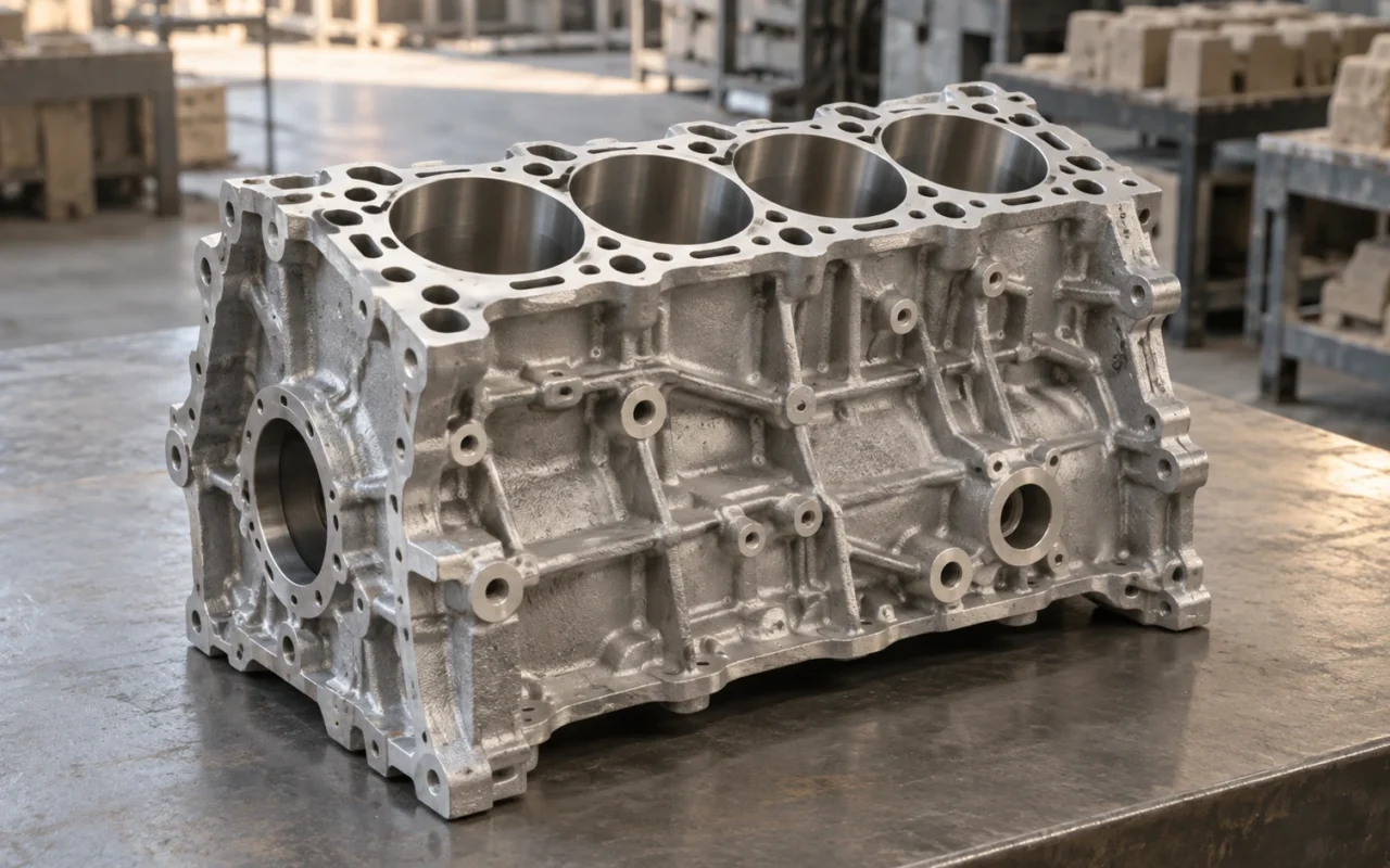
How are internal coolant passages formed in an engine block?
How are the coolant passages inside an engine block made? For water jackets and other cavities formed with sand cores, the foundry first makes a core with the required shape and locates it in the mold. Molten metal fills the space around it. Once the metal has solidified and the core has been removed, the space previously occupied by sand becomes an internal passage.
The challenge is that these passages lie within the metal, and their shape, wall thickness, and position affect how the part functions. A core must be manufacturable, withstand handling and assembly, remain in position during pouring, and be removable afterward. More complex passages bring more manufacturing conditions into the assessment.
3D sand printing offers another way to make cores. It builds molds and cores layer by layer from prepared CAD data, reducing some complex geometries’ dependence on core boxes and segmented assembly. Its value extends from cavity design to casting preparation; the final metal block still requires pouring, machining, and appropriate validation.
Distinguish the block, the head, and the internal passages
The cylinder block and cylinder head are different components, and their internal structures and manufacturing routes may differ. Experience with printed cylinder-head water-jacket cores can inform a block project, but the specific geometry, materials, and production conditions still need a fresh assessment.
Depending on the engine architecture, the block incorporates or helps form cylinder-related structures, crankcase regions, and fluid paths. Coolant passages, lubrication passages, and assembly holes should not all be treated as the same type of cast cavity. Some are produced later by drilling or other machining.
When reviewing a manufacturing route, separate the model by function: load-bearing metal, coolant space, lubrication paths, and openings needed for assembly or machining. Then decide which features will be formed by cores, the outer mold, or machining.
That is more useful than starting with a goal of printing the entire interior as one piece. Casting process design aims to deliver a part that meets its requirements, rather than assign as many features as possible to a single operation.
How do cores form cavities, and where are the difficulties?
A sand core defines the cavity’s shape and must remain correctly located throughout production. A small displacement can make one metal wall thinner and another thicker. External dimensions may appear acceptable even though the internal wall-thickness distribution has changed.

The core therefore needs suitable core prints or another approved locating and support arrangement. Core prints are process features that locate the core relative to the outer mold. They cannot be omitted by designing only the final passage contour.
Core extraction, cleaning, handling, and mold closing impose mechanical loads; pouring adds the effects of molten metal and heat. Slender connecting sections deserve particular attention. Making a core successfully and getting it intact to the pouring stage are separate assessments.
SFSA’s steel casting design guidance relates core size, surrounding metal sections, and bending risks associated with buoyancy. Steel casting parameters should not simply be transferred to engine components. The relevant principle is that a core requires load assessment as well as geometric definition.
The core must also be removable after pouring. Eliminating every cleaning access point to achieve a more intricate passage can prevent an acceptable channel from being obtained, even if the earlier manufacturing steps succeed. Residual-sand inspection and cleaning validation belong in cavity planning from the outset.
Why are complex cores often made in separate pieces?
Conventional core-making must account for core-box construction, filling, curing, and core extraction. If a complex shape cannot be removed directly, it may be divided into several cores that are located and assembled into a complete core package.
Splitting a core is not inherently an outdated approach. It can help manufacturing and handling or fit a mature production line. However, more pieces generally mean more mating interfaces and assembly steps to control. Assess joints, location, and tolerance accumulation rather than comparing part counts alone.
Different engine variants may require changes to core boxes. While internal passages are still being developed, design revisions can affect tooling, cores, and subsequent validation together. This is one situation in which direct printing deserves consideration.
A stable, established conventional core package does not necessarily need to be replaced in full. Identifying the section most constrained by extraction, most frequently revised, or most difficult to assemble can make the comparison clearer than changing the manufacturing route for every sand component.
Which manufacturing problems can 3D sand printing help address?
Binder jetting forms three-dimensional structures by selectively bonding granular material layer by layer. NIST’s process overview explains this basic principle. In sand casting, the output is a designed sand mold or core, not the final metal component.
For complex cavities such as water jackets, printing reduces some cores’ dependence on extraction directions imposed by conventional core boxes. More passage shapes can therefore enter the manufacturing assessment. Some previously separate cores can also be combined, provided strength, loose-sand removal, and assembly conditions are satisfied, reducing selected assembly interfaces.
Identification, location, handling, and venting features can also be considered together in the digital design. Their presence in a model is not sufficient: the actual sand components still need strength, cleaning, and assembly checks.
During printing, the surrounding unbound sand supports the structure. Once unpacked, a sand component must rely on its own strength for handling and assembly. Enclosed or winding regions also need routes through which loose sand can be removed.

The public abstract of SAE’s paper on additively manufactured casting molds specifically discusses the relationship between parting and unbound-sand removal. Reducing extraction constraints still leaves a need to design for cleaning and casting; it does not remove every geometric limitation.
Reproduce the existing core or redesign the coolant passages?
These are two different levels of project.
The first retains the original functional geometry while changing how the core is made. It can support evaluation of core-box replacement, missing tooling, or small-batch production. The key comparison is whether dimensions, strength, surface condition, assembly, and casting results meet the original requirements.
The second uses the new manufacturing conditions to redesign the cooling structure. The project then concerns both making the component and changing its functional design.
More winding passages, a larger passage area, or a location nearer a hot region do not automatically improve cooling. Flow distribution, pressure loss, local temperatures, metal wall thickness, and structural requirements need to be assessed together. Improved manufacturability allows more designs to become candidates.
Manufacturing-route trials and performance-optimization trials should therefore have separate objectives. The former can start with a comparison using identical geometry. The latter requires the engine design team to define thermal-management and durability validation. Introducing both changes at once makes it difficult to attribute improvements to printing.
For example, one trial can retain the passage contour while comparing dimensions and casting behavior from different core-making methods. Once the basic manufacturing conditions are established, passage redesign can follow. This makes results easier to interpret and subsequent issues easier to trace.
Two public examples: restoring a historic block and producing cylinder heads
ExOne’s published restoration case for a historic Delage racing-engine casting involved measurement and scanning of a damaged original, CAD reconstruction, and redesigned printed sand molds. It also describes a plastic model for fit checks and trial casting, rather than an immediate replacement casting straight from a scan. This was a specific historic-part remanufacturing project, not a route that can be assumed suitable for every engine. Read ExOne’s Delage engine casting case study.
A different type of evidence comes from modern production. In its Landshut plant information published on April 18, 2024, BMW describes printed sand cores used for several cylinder-head variants, showing that the technology can enter ongoing production. The components were cylinder heads, with dedicated equipment, inorganic binders, and a production system. Other equipment needs to be assessed against its own conditions. See page two of BMW’s official plant investment statement.
The examples address different tasks: restoration of a particular historic block and ongoing cylinder-head production. For the block projects discussed here, the useful lessons concern data preparation, process design, and validation. Lead time, cost, and capacity still require assessment for the actual project.
What still needs to happen after the core is printed?
Printing the core completes one step in the manufacturing chain. Material and coating condition, venting, outer-mold assembly, melt quality, pouring, and feeding still influence the casting together.
Combining cores may reduce selected joints but make the complete core larger and harder to handle. More complex venting can offer new paths, yet cannot work as intended if loose sand remains or assembly features block the outlets.
Post-casting machining also matters. Final cylinder bores, bearing-related features, mating faces, and other critical details need operations and inspections suited to the design. A core close to its target dimensions does not automatically establish acceptable functional relationships after machining.
Process variation must also be considered. One successful print and one successful casting trial provide useful information but cannot demonstrate batch consistency in ongoing production. Material batches, environmental conditions, machine state, and operating methods need traceability.
A foundry comparing conventional and printed core packages can record core counts, assembly time, inspection methods, cleaning difficulties, and casting results in a comparison table. This helps identify where benefits occur and whether work has shifted to another operation.
How should validation progress from sample cores to an engine?
Each stage of a printed-core evaluation should answer a specific question: can the model be manufactured, can the core be assembled intact, is the trial casting acceptable, and can the machined component meet its intended requirements?
First, review the digital proposal. Confirm the finished-part and casting-blank revisions, then check cavities, wall thicknesses, core prints, cleaning access, and printability. Resolve geometric conflicts in the design before proceeding.
Second, check the sand components and their assembly. Measure critical features and record loose-sand removal, treatment, handling, and mold-closing behavior. An assembly model may help verify the sequence, but a successful fit does not establish how the actual core will behave during pouring.
Third, inspect the trial casting. Select dimensional measurement, internal inspection, or sectioning for the locations at risk, checking wall thickness, passage position, local defects, and residual sand. Nikon’s CT inspection overview lists internal-passage and wall-thickness measurement applications, but the ability to detect a particular issue still needs confirmation.

Fourth, complete machining and the specified functional tests. Leak-tightness, flow, and other checks should use approved conditions and state the sample’s scope of applicability. Passing one test demonstrates only compliance with that test’s requirements.
Assembly or engine validation required by the project follows, performed by a qualified team under an approved plan. Acceptable geometry, a passed pressure test, and proven engine durability are different conclusions and cannot replace one another.
Revision records are particularly important at every stage. If a passage is modified after casting, results from the previous revision cannot silently be carried over. Clear revision relationships are as much a part of reliable development as printing accuracy.
For further mold-design review, see parting, gating, risers, and venting considered together. For aluminum-alloy projects, continue with the quality-control limits of aluminum sand casting.
How do you assess suitability for prototypes, small batches, and volume production?
Projects with complex interiors, frequent core-box changes, small quantities of several design revisions, or missing original tooling are worth assessing for printed cores. Being a candidate for assessment does not justify promising cost or lead time before reviewing the drawings.
For components with a stable high-volume process, compare the complete production systems. Printing time is only one factor; loose-sand removal, post-processing, assembly, inspection, and material circulation can all affect the actual cycle.
When introducing a core into an existing outer mold, start with three interfaces: geometric location within the mold cavity, contact with site handling tools, and compatibility of materials and coatings with the existing pouring process. Each needs an assigned owner and recorded checks. An unchanged exterior does not guarantee unchanged handling, particularly if core weight, center of gravity, or weak sections differ.
For multi-piece core packages, assess more than whether the parts can be combined. Consider how much must be remade after local damage and whether inspection can detect critical defects. A few manageable modules can sometimes be more appropriate than complete consolidation. See assessing consolidation and separation of complex cores for the method, and the automotive development guide to sand printing for organizing prototype and small-batch work.
To evaluate printed cores, share part and core-package CAD data, the alloy, critical dimensions and cavity requirements, quantity, and the current process with the Cprint 3D team. These inputs support discussion of mold and core manufacture using the SJ-1200, identifying suitable trial cores and the interfaces and operations that need sample validation first.
For discontinued or historic parts, original data and design reconstruction also need attention before manufacturing. The preparation can be reviewed alongside reverse engineering and casting when drawings are unavailable.
Frequently asked questions
Is the engine block itself printed directly by a 3D printer?
Not in the route discussed here. The printer produces sand molds or cores; the final metal component requires casting and subsequent operations. Direct metal additive manufacturing is a different route.
Are all passages in an engine made with sand cores?
No. Passages and holes may be formed by casting, drilling, or other machining, depending on the design. Not every internal opening can be attributed to a printed sand core.
If cores can be combined, is the lowest part count always best?
Not necessarily. Consolidation can reduce selected interfaces but also changes handling, cleaning, assembly, and the extent of scrap following damage. Compare the complete manufacturing outcome, not part count alone.
Are printed sand cores only suitable for prototypes?
No. Public examples include dedicated production systems. Ongoing production still requires suitable equipment, materials, automation, quality control, and economic validation; one case does not establish suitability for every system.
Can a part be installed in an engine once a passage sample passes its tests?
That cannot be assumed. Define the conditions and purpose covered by the tests, then complete further validation required by the product. Safety and durability conclusions in particular need confirmation by the professional team responsible for that product.