

From finished-part CAD to a pourable sand mold
A pump-housing CAD model can define its outer shape, flanges, and internal passages accurately. Casting that shape requires further decisions: how the mold opens and assembles, how the core is secured, where metal enters, how liquid metal reaches shrinking regions during solidification, and where gases escape.
Parting, patterns, gating, risers, and venting are five connected elements of sand mold design. Moving a parting plane can change core placement; relocating a gate can alter local thermal conditions; changing a core can affect both venting and sand removal.
Keep three levels distinct. The finished-part model defines the final requirements. The casting blank includes machining stock and process allowances. The mold design adds cores, gating, risers, and assembly features. The sand casting process guide explains the complete production route; here, the focus is how these five design elements work together.
1. Parting determines how the mold is made and assembled
A parting surface is the interface between mold sections; the parting line marks that separation on the casting. A common horizontal arrangement uses a cope and a drag, closed after the cores are placed. The AFS metalcasting glossary defines these basic terms.
Conventional molding first requires a way to withdraw the physical pattern. Draw direction, undercuts, and local projections influence mold divisions and may require loose pieces or additional cores. A layout that is easy to mold should also allow practical core placement, inspection, and location.
For a pump housing with a sealing flange, assess how mold mismatch and flash affect machining if the parting line crosses the sealing surface. Confirm the stock allowance and machining datums. Where several sand components jointly establish a critical dimension, document their locating relationships.
Compare parting arrangements together with casting orientation. One orientation may simplify core placement, while another offers better gate or riser locations. The SFSA example of mold orientation selection considers parting, metal flow, and core location together. The choice for an actual component must reflect its own geometry.
Walk through manufacturing and assembly during review: how the pattern comes out, where the core goes in, whether locating features can be inspected, and which areas become inaccessible after mold closure. This often exposes issues that a section drawing alone misses.
2. Patterns and process models need the right allowances
A pattern is the tool that forms the cavity in conventional molding. Its geometry generally differs from the finished part through dimensional compensation, machining allowance, draft, fillets, and core-support features.
Dimensional shrinkage compensation accounts for size changes as the casting cools. Select it for the alloy, geometry, and manufacturing conditions. Where distortion is a concern, use previous measurements and trial results. Uniformly scaling the entire part can suit particular conditions, but critical dimensions still need checking.
Machining allowance leaves removable metal on surfaces, holes, and datums that require machining. A pump-housing sealing face needs sufficient stock, with clamping and location also considered. Excess stock adds metal and cutting work and changes local thickness. Foundry and machining teams should therefore agree on the blank geometry.
Draft helps release a conventional pattern or core box from the sand. Fillets and wall-thickness transitions require consideration of molding, service loads, and local thermal conditions. Their functions differ; identify which features belong to the finished design and which are manufacturing additions.
Core prints provide the locating and support provisions for a core. Review the prints, their seats, and the surrounding mold together. Check how core movement is restrained and how stability is maintained during pouring. Nearby openings may also serve venting or later sand removal.
Distinguish two responses to shrinkage: dimensional allowance modifies geometry, whereas riser feeding supplies liquid metal during solidification. Review them separately. The guide to casting shrinkage and defect control explains the differences between shrinkage cavities, dispersed shrinkage, and gas porosity.
Direct sand printing can eliminate the physical pattern, but still needs casting-appropriate blank, cavity, and process data. Store finished-part, blank, and mold models separately, identify the production revision, and record allowance changes. The SFSA steel casting design guide also connects machining stock and clamping with cooperation between the customer and foundry.
3. Gating controls how metal enters the cavity
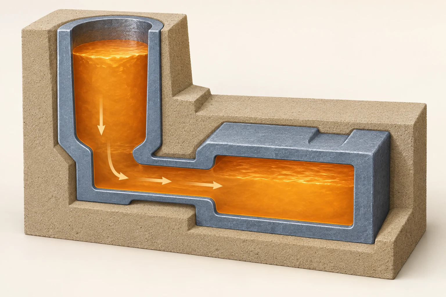
The gating system carries molten metal into the mold cavity. Typical elements are a pouring basin or cup, a downward sprue, runners that distribute metal, and ingates connecting the system to the cavity.
When locating ingates, follow the flow path and the order in which regions fill. For a pump housing, assess whether thin ends fill in time, whether cores around passages face concentrated erosion, and where gas entrainment may occur.
Consider filling speed together with temperature loss, effective pressure head, and flow behavior. Entry area, bends, and branches all matter. The same channel proportions can behave differently with another alloy or geometry. The AFS gating and riser course overview identifies momentum, turbulence, and fluid dynamics as foundations of gating design.
Filters can help remove inclusions and improve flow. Match filter selection and installation to the alloy, flow rate, and gating layout. Foseco’s filters and gating systems information describes alloy-specific options. After adding a filter, check the filling conditions of the complete system.
Gates also affect cutting and finishing. Leave access at connections and coordinate their positions with machining datums and vulnerable features. Review both how metal enters and how the added metal will be removed after casting.
4. Risers need an effective feeding path
A riser holds liquid metal to feed regions that shrink during solidification. Effective feeding depends on the available reserve, thermal conditions, and a connection that stays open for as long as feeding is needed.
A pump-housing mounting boss may form a local heavy section. If a thinner region separates it from the riser, check whether that connection freezes too early. A nearby riser only helps if liquid metal can actually reach the target. The SFSA steel casting design guide illustrates how early freezing of thin sections can cut off heavier regions.
The relationship between volume and effective cooling area supports preliminary thermal comparisons. Actual design also depends on alloy, sand, contact conditions, and auxiliary materials. Steel, aluminum alloys, and graphitizing cast irons solidify differently and need appropriate process judgment.
Insulating or exothermic sleeves can keep a riser’s metal liquid longer. Chills increase local heat extraction and help adjust the solidification sequence. Foseco’s feeding-system information and the SFSA solidification-control example describe these respective functions.
First satisfy casting quality requirements, then compare gating and riser weight, remelting, and cleaning work. Evaluate metal yield alongside the proportion of acceptable castings. Oversized risers add process metal; premature reduction can compromise feeding. Position and connection are often as important as volume.
5. Venting requires a continuous escape path
Separate the sources of gas: air already in the cavity, gases released as molds, cores, and binders heat up, and gas within the melt itself. The first two require escape routes through the mold; melt gas also calls for appropriate metal-quality control.
Vents and sand permeability both influence escape. Dedicated channels provide defined routes, while the sand’s condition affects flow through its body. The AFS metalcasting glossary defines venting and permeability separately.
For a hollow pump housing, trace the path from inside the core through core prints, assembly interfaces, and external outlets. A visible passage in an individual core may still be blocked by locating features, sealing materials, or another sand component after closure.
Coating, drying, and assembly affect the actual conditions. The guide to foundry sand, binders, and reclamation provides material context. Confirm venting requirements for the specific materials and treatments selected.
Printed cores can incorporate vent passages in their digital design. Check loose-sand removal, adequate core strength, and the risk of metal entering the channels during pouring. The number of vents should serve a complete route; it is not a standalone measure of design quality.
Check post-print depowdering and post-casting sand removal separately. The former removes unbound sand; the latter removes core residue from the casting. A small passage that lets gas through may not provide sufficient cleaning access.
6. What changes when sand molds are printed directly?
Direct printing reduces constraints from physical patterns, core boxes, and draw directions. It creates design options for complex geometry, core consolidation, and internal venting. ExOne’s public sand printing service information describes these process capabilities.
The review priorities consequently change:
| Design element | Review focus for direct printing |
|---|---|
| Parting | Choose divisions and locations for build space, depowdering, handling, core placement, and assembly |
| Pattern | Derive blank and cavity data from finished-part requirements; identify compensation and production revision |
| Gating | Assess freer channel geometry, validate filling, and plan removal |
| Risers | Coordinate process features, hot spots, and feeding paths; validate actual solidification |
| Venting | Check outlets, depowdering access, sand-component strength, and continuity after assembly |
Core consolidation can reduce assembly interfaces while changing handling and internal cleaning. Decide over the complete production route, with consolidation and separation of complex cores considered together.

Manufacturing routes can also be combined, for example with a conventional outer mold and printed cores. If internal passages present the main difficulty, compare this combination with printing the complete mold set.
Cprint 3D’s SJ-1200 sand 3D printer makes sand molds and cores for casting. Printed sand components then undergo inspection, assembly, and pouring; the final metal component is produced by casting.
7. Connecting the five elements in a pump-housing example
Consider a hypothetical housing with internal passages, a machined sealing face, and a locally thick mounting boss. This example explains design relationships and does not represent a delivered project.
First define the finished-part requirements: machining of the sealing face, open internal passages, and critical mounting dimensions. Mark them on the finished-part model before developing the blank and process features.
Second compare parting and core location. One arrangement may simplify placement but put a critical surface across the closing interface. Another may preserve dimensional relationships while making placement harder. Record how each option is manufactured, assembled, and inspected.
Third arrange the metal path. Follow flow around the core into thin regions and identify last-to-fill areas and likely concentrated erosion. Check whether ingate removal affects sealing-face machining or clamping.
Fourth check feeding of the thick boss. If changing casting orientation improves the riser connection, recheck parting, core location, and vent outlets at the same time. An orientation change affects several elements, so updating only the riser drawing is insufficient.
Fifth confirm venting and cleaning. Trace where internal passages lead after closure and whether residual sand can be removed through the available openings after casting. For complex interiors, compare split cores or suitable additional cleaning access.
Finally compare conventional molding, a conventional outer mold with printed cores, and a fully printed set against the same requirements. Include tooling preparation, sand-component manufacture, assembly inspection, and subsequent machining. Select the route from part requirements and validation results.
8. Validate with simulation and first-article trials
Proceed through process modeling, filling and solidification simulation, an initial casting trial, physical inspection, and design revision. Simulation helps locate risks and compare options; inputs must represent the actual alloy, sand, and pouring conditions. MAGMASOFT’s public feature overview includes filling, solidification, and thermophysical data among the important simulation inputs and functions.
Before the trial, check dimensions and identification, core integrity and stability, closure interference, depowdering, and vent continuity. A channel in the printing data must also exist as an effective path in the physical component.
Align first-article inspection with the requirements. Check critical dimensions, machining stock, and passage cleanability. Select radiography, CT, local sectioning, or functional tests according to material, critical features, and delivery requirements. Appearance, dimensions, and internal quality answer different questions.
Map any defect back to the process model and analyze the trial record. For each revision, record both changes and conditions held constant so results can be compared. This progressively establishes production conditions appropriate to the component.
20 questions for the pre-production review
Design, foundry, machining, and inspection teams can use this list to organize their review. Set acceptance criteria for the specific project.
- Are the alloy, delivery condition, and service requirements clear?
- Are critical dimensions and measurement datums identified?
- Does machining stock suit final dimensions and clamping?
- Do wall thicknesses and transitions meet service and casting needs?
- Do parting or printed divisions allow manufacture, depowdering, and handling?
- Do core prints and locating features support the core stably?
- Can core placement, inspection, and closure follow the proposed sequence?
- Have cross-interface dimensions, mismatch, and sealing been checked separately?
- Is the main metal path into the cavity clear?
- Have thin ends, erosion, and gas entrainment been assessed?
- Is there a design basis for hot-spot feeding and connections?
- Is there access for gate and riser removal, with machining datums considered?
- Can core gases follow a complete path to the exterior?
- Do sand, coating, and drying conditions suit the venting arrangement?
- Can weak sand features withstand lifting, handling, and pouring?
- Are post-print depowdering and post-casting cleaning each feasible?
- Do finished-part, blank, and process data share the production revision?
- Do simulation material data and boundary conditions represent the process?
- Does first-article inspection cover critical features with clear criteria?
- Are trial conditions, design changes, and follow-up validation recorded?
9. Frequently asked questions
Does sand 3D printing eliminate parting and assembly?
Direct printing reduces conventional pattern-withdrawal constraints. Actual molds may still need multiple sections for depowdering, core placement, handling, or build-space limits, with appropriate location and assembly design.
Are patterns and draft still needed for direct printing?
Printing a mold or core directly can eliminate its physical pattern or core box, allowing reassessment of draft required solely for withdrawal. Conventionally molded sections still need their manufacturing provisions. Fillets, wall thicknesses, and process allowances must also be confirmed.
Are bigger risers and more vents always better?
Size risers for position, connection, and solidification conditions. Design vents for continuous paths, sand strength, and cleaning access. Increasing volume or hole count alone may not improve the complete arrangement.
Can software-generated gating and risers go straight into production?
Review software results, inspect the sand components, and validate with an initial casting trial. Actual materials and process conditions, the production-data revision, and inspection requirements must all be implemented in the production plan.