
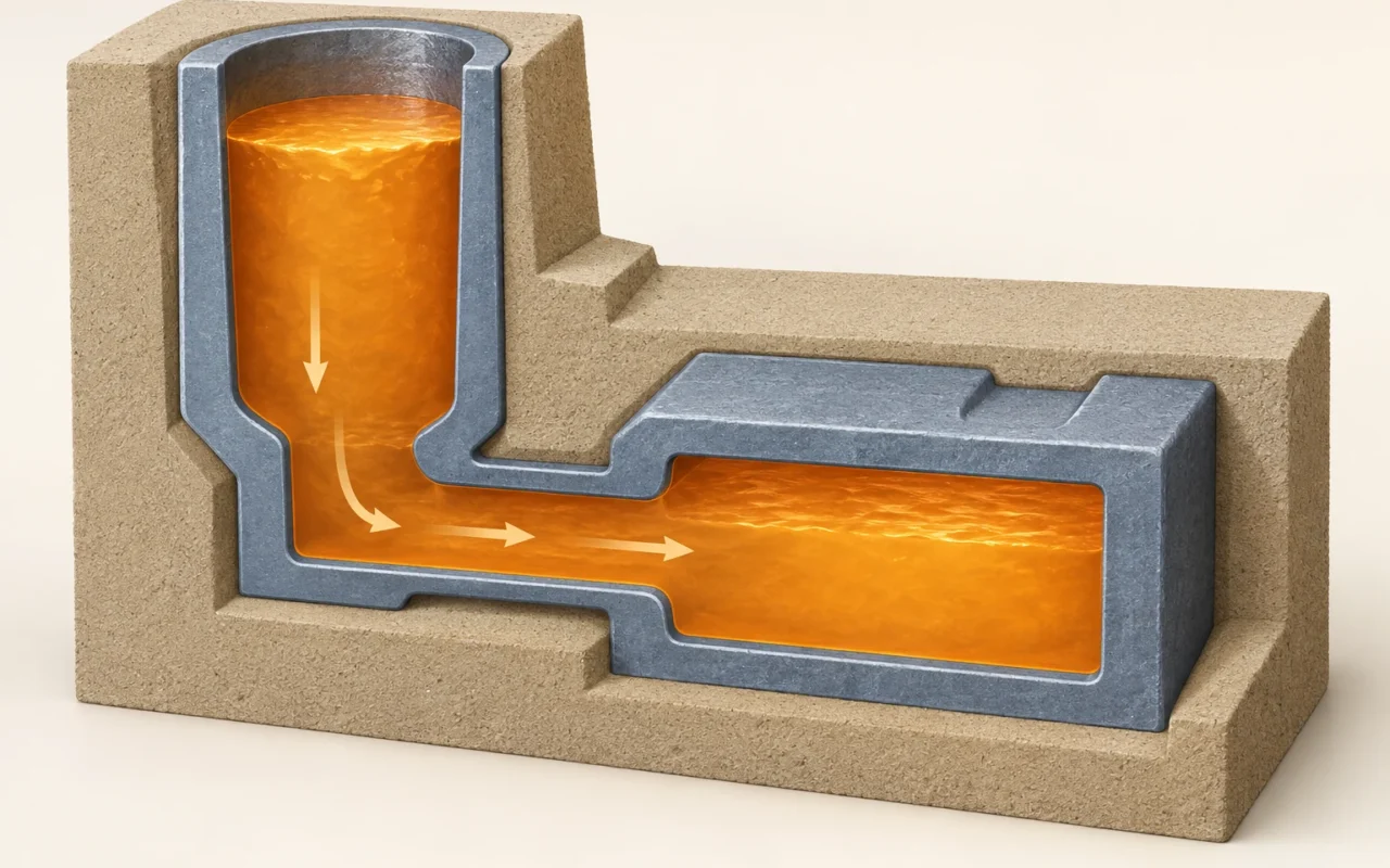
Imagine two situations: a casting looks normal after cleaning, but machining a thick section exposes cavities; another shows no abnormality in an internal inspection, yet a critical dimension is undersize. Both may suggest “casting shrinkage,” but deciding what to do requires separate investigations.
Casting shrinkage involves volume changes as metal cools and solidifies. Whether dimensional compensation is appropriate, whether enough liquid metal reaches a region during solidification, and whether gas is involved lead the investigation toward different process stages. Distinguishing these issues before enlarging a pattern, changing a riser, or treating the melt gives each change a clear purpose.
1. What is casting shrinkage? Separate dimensional changes from an internal shortage of metal
Between pouring and cooling to room temperature, metal undergoes liquid cooling, solidification, and solid-state cooling. Shrinkage needs consideration throughout this sequence for most casting metals, but the effects differ at each stage.
Liquid metal changes volume as its temperature falls. During solidification, liquid becomes solid, and many alloys undergo solidification shrinkage. If a region needs additional liquid metal but cannot receive it in time, cavities may remain. Once solid, the casting continues to change dimensions as it cools, affecting lengths, hole spacing, and other drawing dimensions.
For an overview of where these stages fit into production, read the complete sand casting process alongside this guide.
Two tasks in process design are therefore easy to confuse. Pattern shrinkage allowance accounts for expected dimensional changes when making the pattern so that the cooled casting approaches the target dimensions. Riser feeding supplies liquid metal from a riser to regions that need it during solidification. They address different problems: enlarging a pattern cannot replace feeding. The AFS metalcasting glossary defines the two concepts separately.
Shrinkage allowance must also be distinguished from machining allowance. The former compensates for dimensional changes; the latter is metal reserved for subsequent cutting. Even with sufficient machining allowance, internal soundness requires a separate assessment.
When discussing a “casting shrinkage rate,” establish what is being measured. Linear and volumetric changes are not the same quantity, and the dimensional compensation used by a foundry also depends on the part geometry and process constraints. SFSA’s guidance on patterns and dimensional allowances notes that different molding methods can produce different casting dimensions from the same pattern.
If a particular hole spacing or local dimension deviates substantially, first examine its geometry, datums, and associated operations. Uniformly enlarging the entire model may change areas that already meet requirements. Recording actual deviations at each critical dimension before considering local compensation provides a stronger basis than adjusting everything with one overall shrinkage factor.
Material differences matter too. For example, graphite formation during solidification in gray and ductile iron can produce expansion that offsets some contraction, but feeding measures may still be necessary. Cast steel, aluminum alloys, and cast iron therefore cannot simply share one assessment. The Foseco explanation of shrinkage describes this difference.
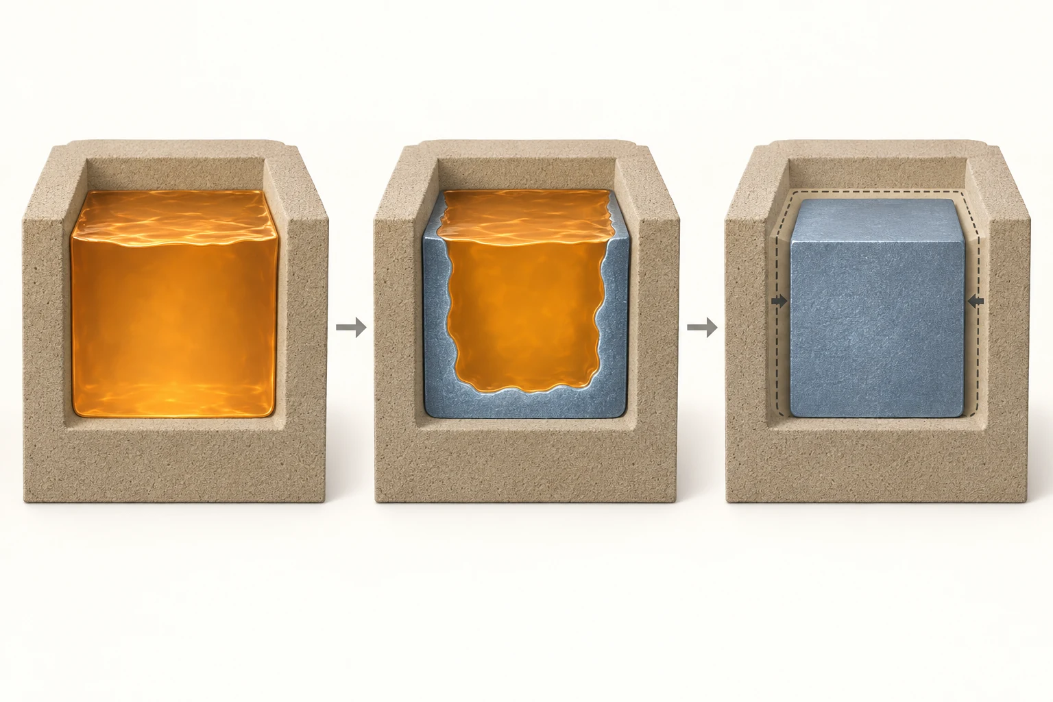
2. Why do shrinkage cavities and shrinkage porosity often occur in thick sections and junctions?
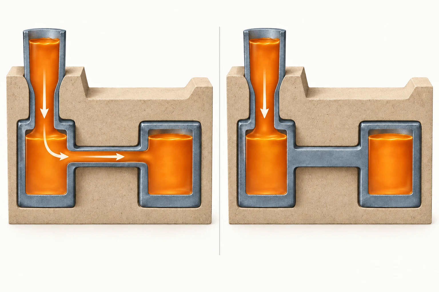
Consider a simplified steel casting: two thick sections are joined by a thinner connection, with a riser on one side. If the thin connection solidifies first while the remote thick section is still contracting during solidification, liquid metal may no longer reach it. Liquid remaining in the riser does not mean it can reach every region that needs feeding.
Thick sections, intersecting walls, and regions that lose heat slowly may become locally last to solidify, commonly called hot spots. Geometry alone cannot identify them reliably: the surrounding molds and cores, cooling conditions, and actual solidification sequence also matter. SFSA’s steel casting design guidance illustrates the risk of a feeding path freezing too early when a thick section is fed through a thin one.
Shrinkage-related voids take different forms. A more concentrated void is generally called a shrinkage cavity; fine pores distributed within a local region are commonly described as shrinkage porosity. Both must be understood in relation to feeding and solidification, rather than separated by an arbitrary pore-size threshold. Some surface depressions can also relate to local shrinkage, but similar-looking depressions still require assessment of the interior.
Understanding fine shrinkage porosity also requires considering the alloy’s “mushy zone,” where solid and liquid coexist. Think of solid dendrites with liquid remaining between them. As solidification progresses, liquid flow channels become restricted, making local feeding difficult and potentially leaving fine pores. The NIST discussion of solidification and casting links these feeding difficulties to microporosity formation.
This suggests a practical way to discuss a design: draw the riser, connecting region, and thick section as one feeding path, then check when each part solidifies. Compared with simply marking “thick wall here,” this helps the team identify locations that need verification. It is a way to analyze geometry; any specific solution still needs support from the process conditions for that alloy.
The same thick section, for example, may have different feeding conditions with a different pouring orientation or cooling arrangement. When discussing drawings, mark the casting’s orientation in the mold, riser positions, and relevant cooling measures together. A part outline alone usually cannot explain why internal cavities occur at a particular location.
3. How can shrinkage cavities, shrinkage porosity, and gas porosity be distinguished initially?
Gas-related pores have several possible sources, including gas entrained during filling, gas dissolved in the melt, and gas generated by molds and cores during pouring. Hydrogen is an important factor in aluminum melt quality control, for example, but it is not a universal explanation for gas porosity in every alloy. AFS’s introduction to aluminum melt cleanliness identifies inclusions and hydrogen-related porosity as separate issues requiring attention.
Pore shape provides clues, but “round means gas, irregular means shrinkage” is too simplistic. In its introduction to aluminum casting defect diagnosis, AFS notes that microshrinkage can be mistaken for hydrogen porosity, directing foundry effort toward a treatment that does not address the actual problem.
First complete the available information, then decide on inspection and verification:
| Observed condition | Information to gather first | Question to resolve |
|---|---|---|
| Cavities repeatedly concentrated in the same thick section | Location map, section geometry, riser and solidification information | Can this region receive continued feeding? |
| Pores at several locations or across batches | Distribution, melt, filling, and mold/core records | Which conditions change alongside the problem? |
| Cavities exposed only after machining | Machining depth, cavity locations, and internal inspection results | Where is the porosity, and how far does it extend? |
Radiography can reveal internal discontinuities in suitable castings; industrial CT can be considered when three-dimensional distribution matters. Sectioning and metallography provide local microstructural information. The method must suit the material, thickness, and pores of interest, and inspectors should state which regions the results cover and what the method can resolve.
Visual inspection assesses only visible areas, and surface penetrant testing cannot prove the absence of internal porosity. SFSA’s guidance on nondestructive testing explicitly distinguishes the scope of surface and internal examinations.
The inspection report must also answer the investigation’s question: were all parts inspected or only a sample, and was the whole casting examined or selected regions? If inspection coverage differs between two tests, “no cavities found” has a different meaning. Recording these conditions in the comparison helps distinguish a process change from a change in inspection.
In practical discussions, record “what was observed” separately from “the suspected cause.” For example, first describe “a cluster of pores at a location beneath the machined surface,” then list causes to verify. This avoids assigning the same diagnosis to an entire batch before sufficient evidence exists.
4. Where should shrinkage and porosity control begin?
Start with part geometry: can local thick sections be adjusted?
Check abrupt wall-thickness changes, rib intersections, and isolated masses, and discuss whether geometry can change while preserving strength and function. Local thinning, altered transitions, or rearranged connections should be assessed with the designer. Fillets also need consideration alongside local thickness: simply increasing a radius does not necessarily eliminate a hot spot.
Purchasing and design teams can help the foundry identify flexibility by stating early which dimensions must remain, which surfaces require machining, and where sealing or loads matter. Adding critical requirements only after sample production often increases rework.
Then examine feeding: can liquid reach the region when needed?
A riser must be suitably located, contain enough feed metal, remain able to feed while the casting needs it, and have an open path. SFSA’s tutorial on riser sizing and placement emphasizes arrangements that let liquid metal reach the region to be fed directly.
Chills can accelerate local heat removal; insulating or exothermic riser sleeves can extend the riser’s effective feeding time. These measures must work with the solidification sequence. Foseco’s guidance on feeding and defect control explains the role of insulation and heat generation, although their actual effectiveness depends on the design.
Why might simply enlarging the riser fail? If the path closes first, storing more liquid does not restore the interrupted supply. If gas is the main contributor to the pores, its sources must also be investigated. Compare not only internal quality but also total metal poured and riser-removal work to determine whether the extra input produces a useful improvement.
Check the melt and pouring: which cause does the change address?
Temperature, filling behavior, melt condition, and treatment records all belong in the investigation. If hydrogen in aluminum is suspected, for instance, assess melt measurements and treatment records together. Seeing pores alone does not establish insufficient degassing.
Pouring temperature cannot determine every outcome on its own. Keep records of where and when temperature was measured, transfer time, and pouring time so that comparable data are used. If temperature, pouring method, and risers change together, record all changes explicitly instead of attributing the entire improvement to one factor.
Check molds and cores: have materials or procedures changed?
For suspected mold or core contributions, review sand, binder, coating, storage, applicable drying requirements, and venting conditions. Different sand systems have different requirements; base the investigation on the materials and work instructions actually used. When selecting printing sand, also compare sand material properties and suitable operating conditions.
Did the problem cluster around a particular core batch, material change, or storage period? A timing correlation should become a lead for verification, followed by testing and controlled comparisons. Such records provide more useful direction than a general instruction to “improve core quality.”
5. What investigation sequence is more effective after pores are found?
AFS’s casting defect analysis course emphasizes systematic investigation. For day-to-day coordination, this can be organized into five steps.
Step 1: define the problem and assessment requirements. Record the part revision, alloy, defect location, and detection method. Replace “holes inside” with a description that can be checked again. Confirm customer or drawing requirements and specify which areas need which inspections.
Step 2: retain samples and batch evidence. Keep defective parts and suitable conforming parts for comparison. Photographs should include a scale and location marks, with inspection results traceable to individual parts. When counting affected parts, record the total inspected and inspection coverage too; do not directly compare percentages from batches inspected differently.
Step 3: propose testable causes. Use location, morphology, and process records to list possible explanations. Suspected underfeeding in a thick section, for example, requires additional solidification and feeding information. Suspected material or operational changes require corresponding batch records. State the missing evidence for each explanation.
Distinguishing “the same location in every batch” from “a sudden increase in one batch” is also useful. The first may prioritize fixed geometry and persistent process conditions; the second warrants reviewing material and operating changes at the time. This sets investigation priorities, but subsequent evidence must still test the causes.
Step 4: arrange controlled changes. Design trials around the leading hypothesis while keeping other conditions as consistent as possible. If several factors will change, plan combinations and recording methods beforehand. For a riser-position trial, for example, record alloy, pouring, and mold/core conditions so that the result can be interpreted.
Step 5: inspect again and confirm repeatability. Use the agreed inspection regions and methods to compare before and after, and check whether the problem has moved elsewhere. Improvement in one part supports further verification; whether later batches consistently meet requirements determines whether to standardize the process.
A shop-floor record should at least include the part and alloy, problem location, batch and process, candidate causes, current changes, inspection method, results, and next action. Designers supply functional and machining requirements; foundries add process details and defect distributions. Discussing the same evidence reduces repeated trial and error.
6. How can 3D printed sand molds help improve the process?
When the investigation points to geometry or a core design, 3D printed sand molds and cores offer a way to trial candidate solutions. For a local internal-cavity change or revised gating and riser layout, consider producing the corresponding molds and cores directly from digital models, reducing reliance on new patterns and core boxes. See the sand printing workflow from CAD preparation to depowdering and post-processing for preparation and handling steps.
Their role concerns how a proposed design is made. The printed products remain molds and cores for casting; pouring, cooling, cleaning, and inspection still follow. Casting shrinkage and gas-related factors must still be included in process design.
When comparing conventional molding with 3D printing, record whether sand, binder, and post-processing conditions also change. If geometry and the material system change together, differences between samples cannot all be attributed to printing. To retain an existing outer mold while changing a complex internal cavity, consider a hybrid approach combining conventional sand molds with 3D printed cores.
Casting simulation can help assess solidification and feeding, narrowing the options to trial; trial castings and inspection establish actual results. A useful approach is to decide in advance which region the trial will verify and how it will be assessed, then choose the appropriate mold-making method. Continue the assessment with the application conditions for sand mold and core manufacturing.
Frequently asked questions
Can a casting shrinkage factor found online be used directly in design?
It can help with material understanding and preliminary discussion, but first establish whether it describes linear or volumetric shrinkage and which alloy and process it applies to. Compensation for a particular part also requires its geometry, molding method, and actual production feedback.
Does finding porosity mean the entire casting must be scrapped?
Assess it against the part’s function, pore location, and agreed acceptance requirements. An inspection indication and an acceptance decision are separate steps. Whether repair is permitted and how to reinspect must also follow the applicable requirements; “the hole is small” is insufficient grounds for acceptance. The SFSA inspection guidance makes this distinction.
How can you tell whether a change worked?
First align inspection methods, regions, and acceptance requirements, then compare samples before and after the change and across subsequent batches. Record both improvement in the original problem and any new issues. Retaining every change helps identify the conditions that support stable production.
Discuss a solution around a specific part
A drawing, alloy information, defect-location records, and an explanation of the existing process provide a stronger basis for discussing casting issues. If you plan to use 3D printed sand molds or cores to test a geometry or mold-making concept, contact Cprint 3D to discuss manufacturing feasibility and sample preparation around your part requirements.