
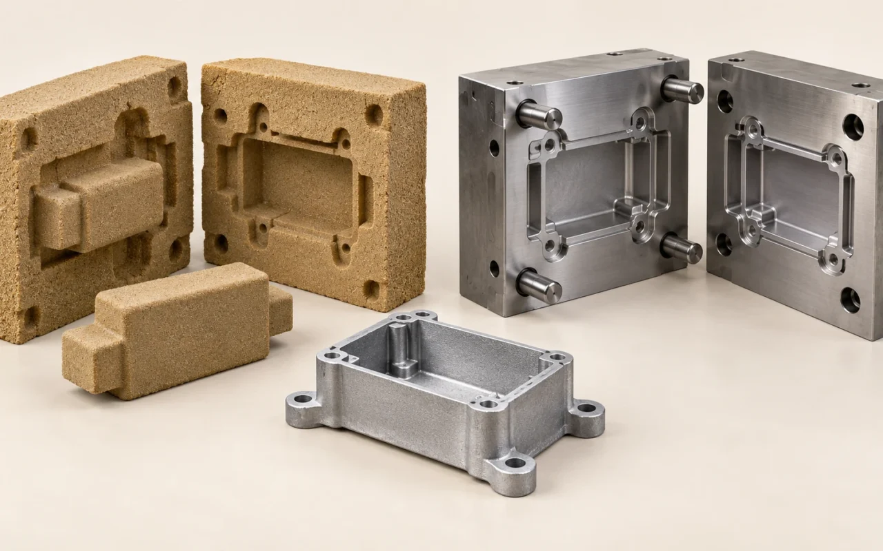
The main differences between sand casting and die casting
An aluminum housing may need repeated interface changes during development and reliable deliveries once production begins. Order quantity alone cannot determine whether to make sand-cast prototypes first or invest directly in die casting tooling.
The main differences lie in how the mold is made and how molten metal fills it. A sand mold is usually broken to remove the casting; high-pressure die casting uses a steel die that opens and closes repeatedly. This affects internal geometry, initial investment, production cycles and later design changes.
First establish the material, geometry and quality requirements, then compare the total cost of the same batch of accepted parts. Here, die casting means high-pressure die casting. Gravity permanent-mold casting, low-pressure casting and squeeze casting use different filling methods and should be assessed separately.
Mold cavities and filling methods
Sand casting uses a sand mold to receive molten metal, commonly by gravity pouring, although some applications use specific controlled filling methods. High-pressure die casting uses an injection system to drive metal into a reusable steel die. the North American Die Casting Association’s technical FAQ identifies reusable steel dies and pressure-driven filling as defining features.
High-pressure die casting includes hot-chamber and cold-chamber processes. In hot-chamber casting, the injection mechanism contacts metal in the furnace. In cold-chamber casting, metal is supplied to the shot chamber from a separate furnace. Aluminum alloys commonly use the cold-chamber process, and equipment must suit the alloy.
The sand mold is usually destroyed during casting removal, so the next part requires a new mold. A die casting tool returns to the next cycle after opening, removal, cleaning and any necessary treatment. The investment is therefore distributed differently: one route continually makes expendable molds, while the other first prepares reusable tooling and the associated production conditions.
| Comparison point | Sand casting | High-pressure die casting |
|---|---|---|
| Mold | Expendable sand mold; make a new mold after each casting is removed | Reusable steel die |
| Typical filling method | Gravity pouring, or a specific controlled filling method | Pressure-driven filling through an injection system |
| Internal geometry | Expendable sand cores are possible; consider positioning and sand removal | Plan die opening, core withdrawal and ejection; assess special core solutions separately |
| Initial preparation | Patterns and core boxes, or directly printed sand molds and cores | Die design, machining, trials and equipment integration |
This does not mean sand casting needs no tooling. Traditional sand casting may still require patterns and core boxes, although these do not directly withstand every pour. Directly printing molds or cores reduces dependence on that upstream physical tooling; it does not eliminate the casting mold itself.
Start by mapping the existing production line. If a plant lacks suitable die casting equipment, melt treatment and tooling maintenance capabilities, buying a die is clearly only part of the investment required to introduce die casting.
Material, size and internal-geometry requirements
Alloy grades and performance requirements
Sand casting supports multiple alloy systems, and high-pressure die casting also offers different material options. However, an alloy commonly used in one route cannot simply be transferred to another without validation.
Drawings should specify the alloy grade, delivery condition and required properties. If the design depends on strength or elongation after a particular heat treatment, confirm that the proposed process can meet those requirements. Being able to form the shape does not establish suitability.
Similar alloy names also do not guarantee the same microstructure or defect levels. When a part carries cyclic loads, provides sealing or serves a connection function, a process change needs a defined validation basis.
Internal passages and core withdrawal
Expendable sand cores can form certain complex internal spaces, but they must be located securely, withstand pouring and be removed afterwards. High-pressure die casting usually incorporates opening, ejection and core withdrawal into the die design. Undercuts and side holes may add mechanical complexity.
This does not make complex hollow geometry impossible in die casting. Special core materials, process combinations and equipment have their own application ranges, but they should not be assumed to be standard capabilities at every supplier.
For a curved passage, ask three practical questions. Can a withdrawing core form it? If an expendable core is used, can it withstand the process and be removed reliably? If the part is split into two assembled pieces, what sealing and connection risks are added? These questions turn complexity into technical conditions that can be evaluated and costed.
Size and wall thickness
Choosing sand casting for large parts and die casting for small parts is too broad a rule. Die casting depends on projected area, clamping capacity, shot capacity, die size and equipment configuration. Sand casting is also limited by flask dimensions, core strength, pouring quantity and handling conditions.
Review thickness transitions, rib-to-wall junctions, and local heavy sections around holes and bosses early. Die casting design generally favors uniform walls and gradual changes where needed; actual thickness depends on the part and process. NADCA’s wall-thickness design guidance emphasizes this approach.
If a foundry proposes a wall-thickness change, ask whether the reason is filling, solidification, release, machining or compatibility with existing equipment. The reason determines how much design change the team can accept.
Surface, dimensions and internal quality
High-pressure die casting is often used for repeatable batch production with less subsequent machining. Sand castings can achieve critical dimensions through machining. Compare specific features and delivery conditions instead of labeling an entire process as high- or low-precision.
For example, a housing exterior may meet appearance requirements while its sealing groove still needs machining. A correctly positioned threaded hole does not prove that the surrounding internal quality meets pressure requirements. Quotations should distinguish as-cast dimensions, final machined dimensions, surface treatment and defect acceptance.
Air entrained during die filling can affect heat treatment and service performance, but die casting processes should not all be treated alike. High-integrity processes, including high-vacuum approaches, require assessment of the alloy, porosity control and delivery condition. NADCA’s public contents for high-integrity die casting standards lists heat treatment and material condition in a separate chapter. Specify heat-treatment or welding requirements during process selection.
Conversely, a sand casting is not automatically free of gas porosity simply because it was made without high-pressure injection. For a closer look at gas-related and solidification-related defects, see distinguishing gas porosity, shrinkage cavities and shrinkage porosity. Define internal-quality requirements by inspection regions, methods and acceptance conditions, rather than a blanket statement that no voids are allowed.
Tooling, first-part lead time and design changes
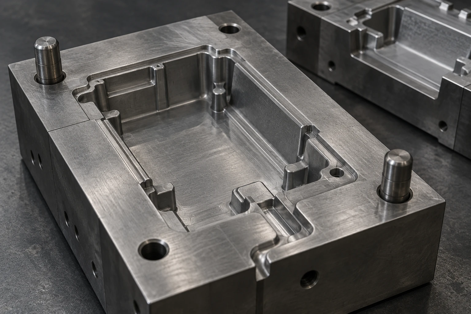
A die casting tool does more than form the outside shape: it must support opening, core withdrawal, ejection, temperature control and equipment integration. Repeated production exposes it to thermal loads and molten-metal erosion, so materials and maintenance affect investment. NADCA’s explanation of tooling costs describes these factors. First-part lead time also includes design reviews, trials, corrections and process confirmation.
Traditional sand casting tooling usually has different structures and operating conditions, but it can still be complex. With multiple cores and long dimensional chains, its upfront investment cannot be dismissed simply because it is not a metal die casting tool.
When the design is still changing, request separate estimates for changes to an ordinary outer wall, mounting positions, core-withdrawal direction and internal passages. These changes can have very different implications for reuse of existing tooling.
3D sand printing makes molds and cores from prepared casting data. Some revisions can be implemented by updating the data and printing again, reducing changes to physical patterns or core boxes. It directly produces sand components; metal parts still require mold assembly, pouring, cleaning and inspection. Internal-geometry changes also require another review of pouring, machining and inspection plans.
This explains why the economical choice during development may differ from the economical choice during production. Development emphasizes small quantities and frequent revisions; production emphasizes cycle time, yield and maintenance under stable conditions. A housing with changing interfaces and passages warrants a comparison of revision time. A part with mature tooling and stable long-term orders warrants closer attention to recurring production and maintenance costs.
Comparing the total cost of a production batch
Align the alloy grade, drawing revision, delivery quantity, machining scope, surface treatment and acceptance requirements before comparing quotations. A raw-casting price cannot be compared directly with a price that includes finished machining and inspection.
Fixed investment may include tooling, process development, trials and equipment adaptation. Variable cost must cover material, molding or die casting, cleaning, machining and inspection, plus the scrap and rework cost allocated to each accepted delivered part. If both routes are technically feasible and meet the same delivery requirements, a simplified model provides a starting point:
Sand-route total cost = sand-route fixed investment + accepted delivery quantity × sand-route variable cost per accepted part.
Die-casting total cost = die-casting fixed investment + accepted delivery quantity × die-casting variable cost per accepted part.
When die casting has higher fixed investment but lower variable cost per part, the two routes may have a cost crossover:
Initial crossover quantity = (die-casting fixed investment − sand-route fixed investment) ÷ (sand-route unit variable cost − die-casting unit variable cost).
This calculation is meaningful only when the denominator is positive, the comparison uses the same scope and costs remain approximately constant over the quantity range. If die casting does not have a lower unit cost, no universal quantity can be calculated at which it must become cheaper.
Real projects also have step changes. A die may need repair or replacement, orders may move into a different capacity range, material prices may change, or new inspections may be required. Re-estimate by stage instead of using a single straight line for the entire product life cycle.
Use actual orders and available capacity, rather than treating theoretical cycle time as year-round full utilization. Build a baseline from quotations, then test lower order volumes, more revisions and reduced yield separately.
A crossover quantity exists only under those conditions. Without real quotations, first list the variables that still need to be costed.

Which routes deserve assessment for different production tasks?
| Project situation | Route to assess first | Conditions to confirm |
|---|---|---|
| Design not frozen; prototypes needed first | Traditional or 3D-printed sand molds | Revision time, first-part requirements and test purpose |
| Multiple models with infrequent replenishment | Sand casting or printed sand molds | Usability of existing tooling and small-batch delivery cost |
| One model with sustained high-volume demand | High-pressure die casting | Suitable alloy and geometry, die maintenance and stable yield |
| Curved internal passages or special quality requirements | Choose according to core and material solutions | Feasibility of making, locating and removing cores, and inspecting the part |
These are directions for assessment. Stable high volume helps spread die investment, but geometry and material requirements come first. Infrequent replenishment makes printed sand molds worth evaluating, including a comparison with traditional tooling that remains usable.
the Aluminum Association’s processing overview notes that, for aluminum applications, sand casting is generally more economical for small quantities, complex designs or very large castings, while die casting is commonly used for high-volume work. The actual choice still depends on plant capabilities and quotations for the specific part.
If investment casting is also a candidate, read the differences between sand casting and investment casting to compare cavity formation, exterior detail and internal-geometry requirements.
What can sand-cast prototypes validate for a die-cast product?
Under appropriate conditions, sand-cast prototypes can help check assembly space, interface positions and design accessibility. If production will use die casting, however, their results cannot automatically establish every production requirement.
Divide the test objectives into three levels. First, geometry and assembly: does the part fit, and do the holes align? Second, function, including flow, sealing and local thermal behavior: record differences in material, wall thickness and surface condition. Third, durability and safety-related properties: these generally require validation using the final material, process and accepted test plan.
Passing a static assembly check answers an assembly question. Even successful short-term operation does not establish fatigue life. Reports should identify the prototype’s manufacturing route, revision and purpose so that later teams do not mistake prototype results for production approval.
If the final process changes, revisit machining allowances, locating datums and fixtures. Similar external shapes can still have different as-cast dimensional distributions and machining behavior. An agreed validation checklist is often more efficient than arguing afterwards about why a prototype cannot represent production.

Frequently asked questions
Is sand casting always cheaper?
No. Initial tooling, molding each part, machining and inspection all affect the result. Compare the total cost of delivering the same batch of accepted parts, rather than raw-casting prices alone.
How long does a die casting tool last?
There is no service-life quantity that applies to every project. Alloy, die material, local geometry, thermal cycling and maintenance all matter. Quotations should define how life is counted, which maintenance is included and when replacement is required.
Can ordinary sand cores be used in high-pressure die casting?
They cannot be assumed suitable. Core strength, gas generation, positioning and eventual removal must suit the actual operating conditions. A team with the relevant capabilities should confirm the specific solution.
How does 3D sand printing help development?
It can reduce the work of making and modifying physical patterns or core boxes when evaluating prototypes, design revisions and complex internal geometry. Casting is still required afterwards, and the final die-cast product must be validated with its own material and process.
How should the alloy and process be selected together?
Assess them together against functional requirements. If several processes remain possible, start with types of metal casting and process selection, then compare the candidates using the alloy grade, geometry and functional requirements.