
How sand casting works
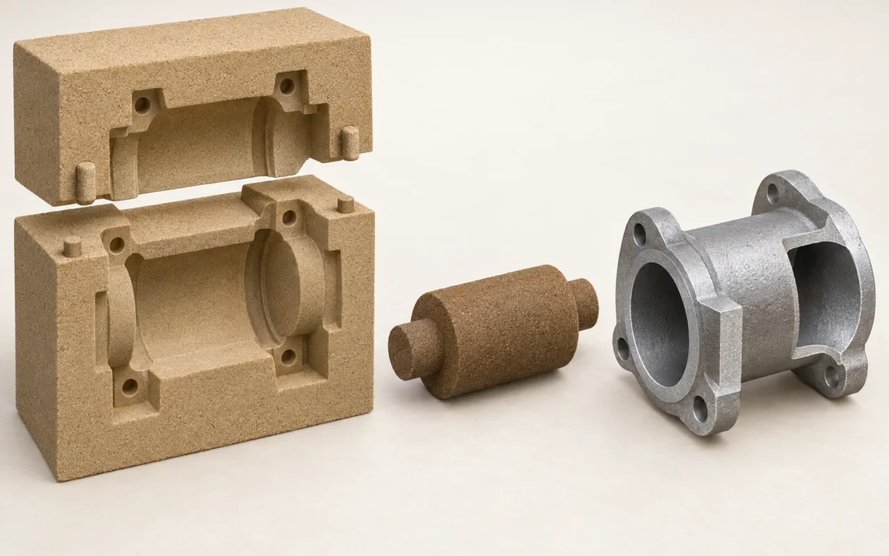
Sand casting is a manufacturing process in which molten metal is poured into a mold made from molding sand. Once the metal has solidified and cooled sufficiently for shakeout, the sand mold is removed to release the casting. The process can produce relatively simple solid parts, while sand cores make it possible to create internal passages and cavities.
Consider a pump housing with an internal flow passage. What forms its outer metal profile? How does a curved passage remain inside? After pouring, how do you determine whether the part is fit for use? Answering these questions starts with the different roles of patterns, sand molds and sand cores, then follows the complete sequence through molding, pouring, solidification and inspection.
1. Distinguish the pattern, sand mold, sand core and casting
These four terms describe different objects in manufacturing and should not be used interchangeably.
| Object | Role in the process | Pump housing example |
|---|---|---|
| Pattern | Tooling used to form the mold cavity in conventional molding | Provides geometry related to the housing exterior, with the adjustments needed for casting |
| Sand mold | Defines the casting shape and contains the molten metal | Encloses the housing exterior and the spaces needed for pouring |
| Sand core | Occupies areas that must remain hollow or are difficult to form directly | Occupies the intended internal flow passage during pouring |
| Casting | The solid metal object obtained after solidification | The cleaned housing blank, subsequently machined and inspected as specified |
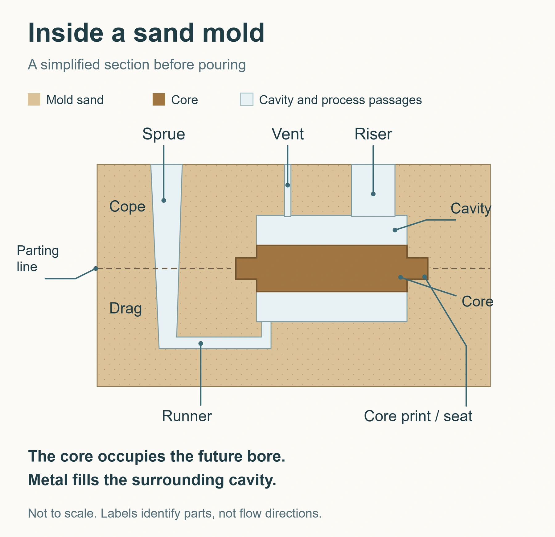
The distinction is that the sand mold is a physical object, whereas the mold cavity is the space left inside it for metal. With a core in place, metal fills the region between the mold and core. Removing the core then opens the internal passage. The American Foundry Society’s introduction to foundry sand also explains mold and core functions in terms of external profiles and internal cavities.
In a common horizontally parted mold, the cope and drag meet at the parting plane, while flasks support the molding sand. Core prints and their corresponding seats in the mold support and locate the core; it cannot simply be placed anywhere in the cavity. Incorrect location can leave an apparently normal outer profile while shifting an internal passage or producing unacceptable local wall thickness.
The mold also needs a gating system to admit metal, risers to supply feeding metal, and passages through which gases can escape. Together with the part cavity, these features form the mold system, each with a different task. Mold design therefore has to address geometry, metal flow, solidification and venting together.
2. What is a sand mold made of, and how does it hold its shape?
Loose sand grains alone cannot readily retain complex shapes. In molding sand, the base sand provides the framework and a binder system supplies the properties needed for molding and pouring. Whether water, curing components or other additives are included depends on the chosen material system.
Two common routes provide a useful starting point. Green sand typically uses clay and water for bonding, while resin-bonded no-bake sand uses a resin system that hardens under the appropriate conditions. “Green” does not mean the sand is green in color, nor does it indicate an environmental rating. These terms appear in the AFS metalcasting glossary.
Selecting sand is about more than hardness. The mold needs enough strength to withstand handling, assembly and the action of molten metal, along with refractoriness suited to the pouring conditions. Gases must be able to escape, and sand should be removable after casting. During molding, the sand must also fill the details around the pattern.
These requirements interact. Retaining fine features, for example, does not automatically make residual sand easy to remove from inside a part. Nor should one sand formulation be applied to every alloy and component without validation. Material selection should consider the foundry sand, binder and sand reclamation arrangements together. For sand printing, see the properties and application conditions of four printing sands.
3. The eight steps of sand casting: from drawing to accepted casting
The process can be understood in eight steps. In actual production, molding, coremaking and melting may proceed in parallel. The sequence below is arranged to explain how the part takes shape.

1. Review part requirements and define the casting route
First establish the material grade, part geometry, quantity and delivery requirements. Critical dimensions, wall thickness changes, machined surfaces and acceptance criteria on the drawing all influence the molding and pouring plan.
For a pump housing with a flow passage, engineers need to understand how that passage will be formed, how flange faces will be machined, and whether pressure or leak testing is required. An exterior model alone cannot provide enough information to locate the core, allocate machining stock or define final acceptance.
This stage should also establish whether the delivery is an as-cast blank or a finished, machined component. Clarifying that scope early helps design, purchasing and the foundry work toward the same result.
2. Convert part geometry into pattern, mold and core designs
The conventional route requires patterns and core boxes; a core box is the tooling used to make a sand core. Direct printing instead requires digital models of the molds, cores and associated process features. Both routes must turn product geometry into a workable casting design.
Three adjustments are easily confused. Draft allows a physical pattern or core to be withdrawn from the relevant tooling. Machining allowance reserves metal for subsequent cutting operations. Dimensional shrinkage compensation accounts for changes in casting dimensions as the metal cools.
They serve different purposes and cannot substitute for one another. Enlarging a model will not eliminate shrinkage cavities caused by inadequate feeding during solidification. Directly printing a sand mold removes the draft constraint associated with extracting a physical pattern, but sand-part removal, assembly, cleaning and final dimensional requirements still need attention.
3. Make the molds and cores, then check their quality
In conventional molding, sand is formed around a pattern, which is removed to leave the mold cavity. Cores are formed in core boxes using the selected process. Curing, coating and drying requirements depend on the sand system and service conditions; no single treatment should be treated as mandatory for every sand part.
Before assembly, check mold and core dimensions, sand surface integrity and locating features. Even a correctly shaped slender core must be strong enough for handling and assembly. Damage that becomes apparent only during pouring can alter a passage or introduce sand into the molten metal.
The aim is to obtain sand parts that can be assembled as designed and meet the requirements of subsequent pouring.
4. Set the cores, close the mold and recheck gating and venting
Core setting places each core at its intended location inside the mold. After providing location, support and any necessary restraint, close the mold and check the assembled condition.
Before closure, three questions should be answered: where will metal enter the cavity, where will feeding metal come from during solidification, and how will gases leave the cavity and cores? Gating directs metal flow, risers provide feeding metal where the design calls for them, and vents help gases escape.
These features should already have been defined during process design. At this stage, check that they have been formed and connected correctly. Whether filters are used, and where they are positioned, should also follow the alloy and filling plan.
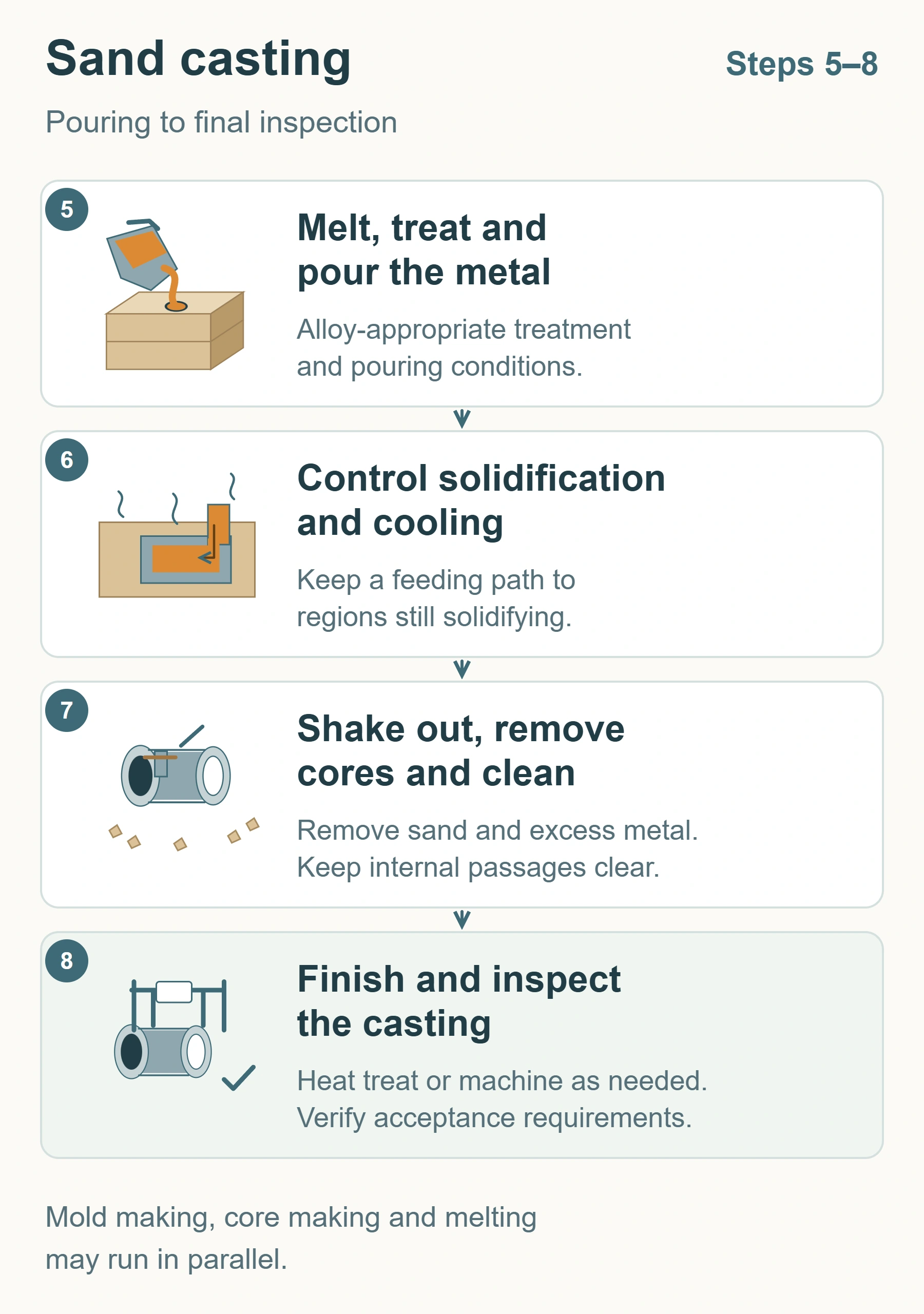
5. Melt, treat and pour the metal
The metal charge is melted, its composition controlled and any necessary melt treatment performed for the selected alloy. The metal is then poured into the prepared mold.
Pouring temperature, melt cleanliness, entry location and the filling process can all affect casting quality. Temperatures and treatment methods must suit the alloy, wall thickness and mold conditions. Aluminum, iron, steel and copper alloys cannot share one universal set of parameters.
For a hollow component such as a pump housing, metal must fill around the core to form continuous walls. A full cavity confirms only that filling has occurred. Internal soundness, core position and dimensional compliance still depend on solidification control and inspection.
6. Control solidification and cooling while maintaining effective feeding
Once metal enters the mold, different regions do not solidify at the same time. Wall thickness, geometry and heat transfer conditions influence the sequence. Wherever feeding is needed, liquid metal must be able to reach that region through an effective path.
For example, a thick section may still need feeding after a thinner connection to its riser has solidified. A nearby riser may then be unable to supply more metal. The Steel Founders’ Society of America’s explanation of solidification and feeding describes this relationship. One aim of directional solidification design is to establish a freezing sequence that supports feeding.
Dimensional change after cooling and internal shrinkage cavities are therefore separate issues. The first concerns dimensional control; the second concerns sufficient metal supply during local solidification. Riser design must suit the alloy and part geometry.
7. Shake out, remove cores, cut off gating and risers, and clean
Once the casting has cooled sufficiently for subsequent handling, it is separated from the mold in the shakeout stage. Cores are then removed, gating, risers and excess metal cut away, and surfaces cleaned as required.
Only after core removal does the pump housing’s internal passage become a usable cavity. Complex passage design must account for how residual sand will leave, whether tools or cleaning media can reach it, and how cleanliness will be checked. A clean exterior does not establish that internal cleaning is complete.
Shakeout normally destroys the mold’s shape, but the sand may enter an appropriate treatment and reclamation process. Reusing sand is compatible with making a new mold for each pour.
8. Heat-treat, machine and inspect as specified
After cleaning, post-processing follows the material and delivery requirements. Parts needing heat treatment follow the specified procedure, while mating, mounting or sealing surfaces are machined to the drawing. The process route determines the sequence of these operations.
Inspection commonly starts with appearance and dimensions, followed by the specified material and property checks. Internal quality or sealing requirements may also call for suitable nondestructive examination, pressure tests or leak tests. The inspection methods and acceptance criteria must match the intended use.
The question is now whether the part meets delivery requirements, rather than whether its shape has been cast. If inspection reveals a problem, records for materials, sand parts, pouring and post-processing should support traceability and subsequent improvement.
4. Which step changes with conventional molding or 3D sand printing?
The main difference is how the sand molds and cores are produced.
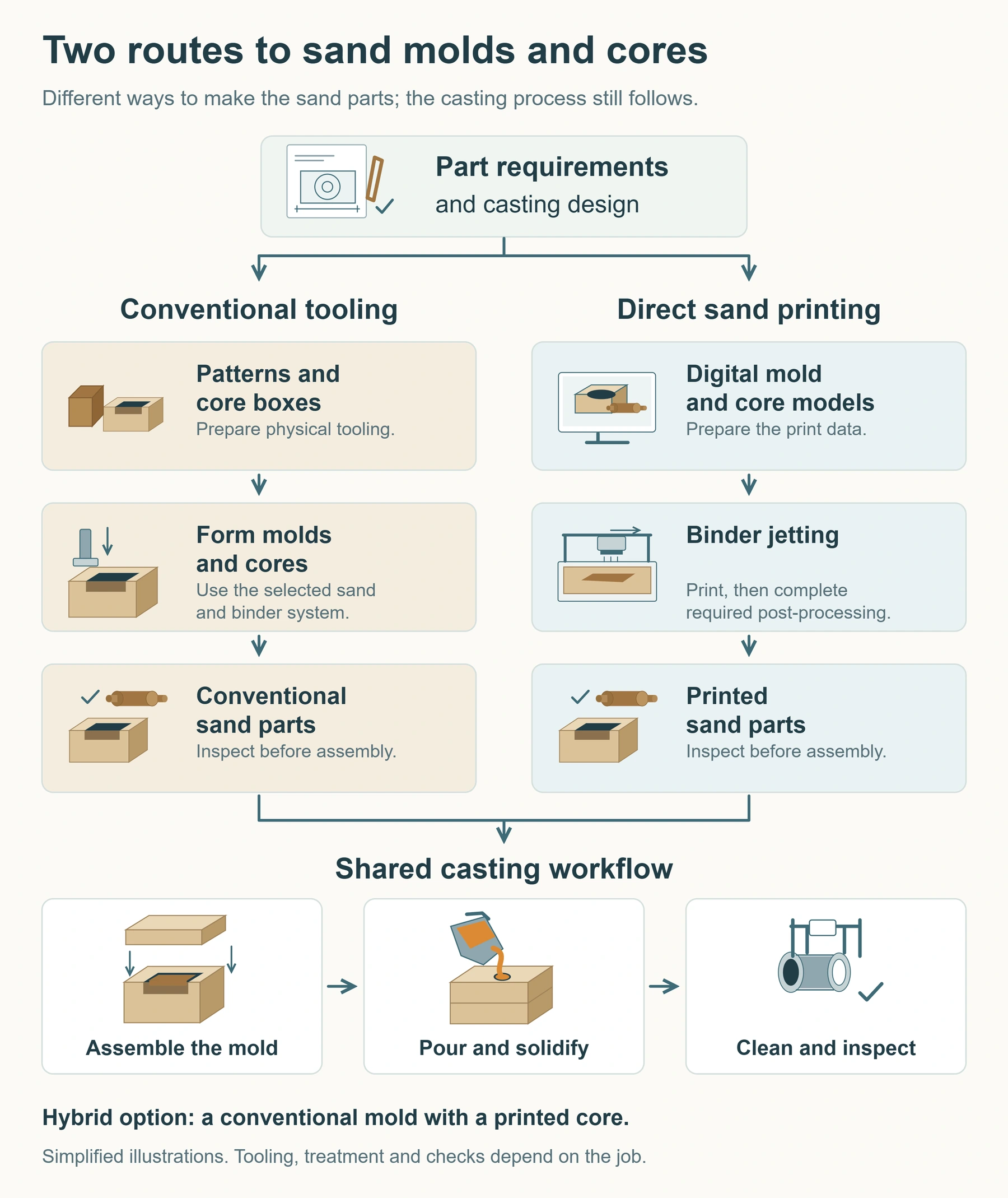
The conventional route first makes patterns, core boxes and other tooling, then uses them repeatedly to form sand parts. Direct sand printing starts with prepared digital models and uses binder jetting to bond sand grains layer by layer. Curing, depowdering and inspection follow the material system’s requirements. NIST’s introduction to binder jetting explains the principle of bonding powder particles with binder; when sand is used, the result is a foundry mold or core.
For the printing stages in detail, see the sand printing workflow from CAD slicing to cleaning and post-processing.
| Comparison | Conventional patterns and core boxes | Direct sand printing |
|---|---|---|
| Initial preparation | Make, prove and maintain physical tooling | Prepare print data and validate the sand and binder system |
| Design changes | Assess tooling modifications or replacement | Revise the digital design, then validate printing and casting results |
| Complex internal cavities | Assess core box construction, core splitting and core assembly | Assess printability, core strength and sand removal access |
| Repeat production | Evaluate existing tooling and molding cycle times | Evaluate printing, post-processing and assembly capacity |
Direct printing can be evaluated for prototypes, spare parts, complex cores and frequent design revisions. For stable repeat production, compare tooling, sand-part manufacture, cleaning and inspection together; quantity alone cannot determine the route. A combination of conventional molds and printed cores can also introduce digital manufacturing where it is useful.
Suppose a pump housing’s exterior stays unchanged while several internal passage designs need testing. Retaining the outer mold tooling and printing different cores may be an option. The review must still check core location against the existing mold, required wall thickness and sand removal for each version. Partial use of printing still requires complete casting validation.
Cprint 3D’s SJ-1200 sand 3D printer makes foundry molds and cores and enters the workflow at this stage. After printing, assembly, pouring, solidification and acceptance checks remain necessary. The dimensional performance of printed sand parts must not be equated directly with final casting tolerances.
5. Which metals and parts can be sand cast?
Sand casting accommodates several alloy families, but the specific route must be based on the material grade and part requirements.
| Metal family | Illustrative part applications | Key conditions to establish |
|---|---|---|
| Aluminum alloys | Housings, engine components and prototypes | Wall thickness, internal quality, heat treatment and machining requirements |
| Cast iron | Machine tool structures, pumps, valves and engine components | Material microstructure, geometry and service properties |
| Cast steel | Valve bodies and mechanical parts in suitable grades | Mold refractoriness, feeding and post-processing plans |
| Copper alloys | Valve and piping components in suitable grades | Alloy selection, service environment and surface requirements |
For example, the Copper Development Association’s C89537 alloy data lists a sand-cast condition and valve-related applications. This does not mean that all copper alloys are interchangeable. Similarly, describing a part simply as an “aluminum housing” is insufficient to define production; the grade, geometry, quantity and acceptance requirements are still needed.
Sand casting is worth evaluating for complex internal cavities, larger integral structures or design validation at relatively low quantities. See sand mold and core manufacturing applications for digital molding possibilities. The final choice must also consider other metal casting processes and subsequent machining routes.
6. Consider the advantages and limitations together
Sand casting covers a broad range of alloys and part sizes, while cores provide a way to form internal passages and cavities. Conventional patterns can be reused, and digital molding adds options for certain design changes and complex core requirements.
Cost advantages depend on the task. The Aluminum Association’s processing overview notes that sand casting can be more economical than die casting and permanent mold casting for some low-volume, complex or large aluminum castings. This should not be generalized into a claim that it is cheapest for every metal and quantity.
The limitations are equally relevant. Sand molds are normally expendable, so molding, sand treatment and cleaning continually use resources. Complex cores need reliable location and adequate access for sand removal. As-cast surfaces and dimensional capability depend on the process, and critical surfaces may still need machining.
To compare how sand and investment casting form cavities, reproduce external detail and handle internal spaces, read Sand Casting vs Investment Casting: What Is the Difference.
A total-cost comparison should include tooling, materials, manufacturing, post-processing and inspection on the same list. Comparing molding costs alone can overlook work that materially affects delivery.
Purchasing teams should also align the scope of competing quotations. A price for an as-cast blank cannot be compared directly with one that includes machining and inspection. Define machined surfaces, internal cleanliness and test requirements so that cost differences can be traced to the process or to different delivery scopes.
7. Where should a defect investigation begin?
When holes, inclusions or dimensional deviations are found, first establish their location and appearance, then review production records to investigate the cause. Similar appearances can result from different problems. A single photograph is insufficient grounds for deciding which process parameter to change.
| Observation | Categories to consider | Next checks |
|---|---|---|
| Holes or porosity | Gas-related porosity, inadequate feeding and other causes | Distinguish using location, morphology, inspection results, and melt and mold records |
| Localized shrinkage cavities or shrinkage porosity | Solidification and feeding problems | Review section changes, late-solidifying regions and feeding paths |
| Sand inclusions or sandy residue | Possible sand erosion or breakage | Check sand surfaces, core integrity and metal entry paths |
| Seam-like areas that have not fused | Filling problems such as cold shuts | Review where metal fronts meet, temperature and flow conditions |
| Offset at the parting line | Mold mismatch or assembly location problems | Check mold alignment; investigate core position separately for internal deviations |
This table guides investigation; it does not replace inspection findings. Adding a riser after finding internal holes may not address gas-related problems, and changing venting alone may not restore an interrupted feeding path. For internal voids, read about the differences between casting shrinkage, shrinkage cavities and gas porosity, then examine the particular part’s feeding paths and process records. Gates, risers and vents should be reviewed together.
8. Five common questions about sand casting
Does every sand casting need a core?
No. A separate core may be unnecessary if the mold itself can form the part. Whether to use cores and how to divide them depends on geometry, parting and the production plan, not simply the size of the component.
Does breaking the mold make the sand unusable?
The mold’s shape is normally used once, but its sand may be reused after suitable treatment and quality checks. The reclamation method, reuse proportion and new-sand additions depend on the sand system and production conditions. Unlimited recycling should not be assumed.
Why is the sand mold usually broken to remove the part?
The mold surrounds the casting, and complex parts may also contain sand cores. Shakeout and cleaning remove these materials to expose the casting and open its internal spaces. The conventional pattern is a separate tool that can make the next sand mold.
Does 3D sand printing directly produce a metal part?
No. Sand printing produces an intermediate component for casting. Melting, pouring, cleaning and other operations still follow. Equipment discussions should distinguish sand-part manufacturing capability from the capability of a complete casting production process.
Is a sand mold the same as a pattern?
Terminology can become confusing when “mold” is used loosely. Here, a sand mold means the sand-based form used for casting, while a pattern means the tooling used in conventional molding. Specifying the object and its function is clearer than relying on a general term alone.
From part geometry to a complete mold design
Four connected questions make sand casting easier to understand: how the shape is formed, how metal enters, how solidification is fed and how gases escape. Together, they determine whether a design can turn a drawing into a casting that meets its requirements.
To evaluate sand mold or core production, gather the 3D model, alloy grade, quantity, critical dimensions and acceptance requirements. Then contact the Cprint 3D team to discuss where sand printing could fit into your existing workflow.