
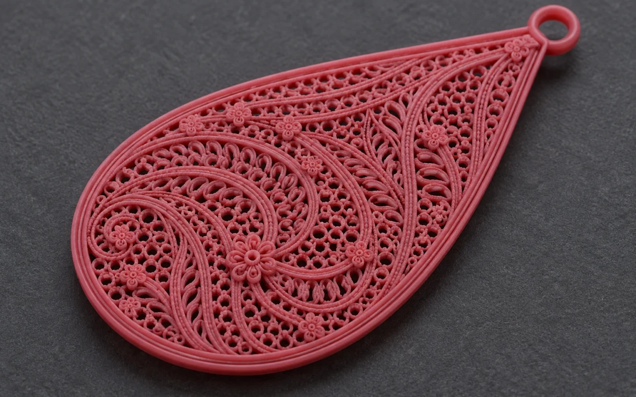
A ring’s openwork design often lies in the interwoven wires of its shank, the basket beneath its setting and the spaces between its motifs. Wax 3D printing provides a way to produce these complex forms. Between the digital model and wearable jewelry, however, come cleaning, handling, sprue-tree assembly, casting and finishing.
A useful design question is how each fine wire will pass intact through every operation. Review connections, openings and tool access together, so that the intended pattern can be checked in the wax pattern, the as-cast metal and the finished piece. The printer produces a pattern for lost-wax casting; casting and further processing produce the final metal jewelry.
1 Inspect the connections and openings
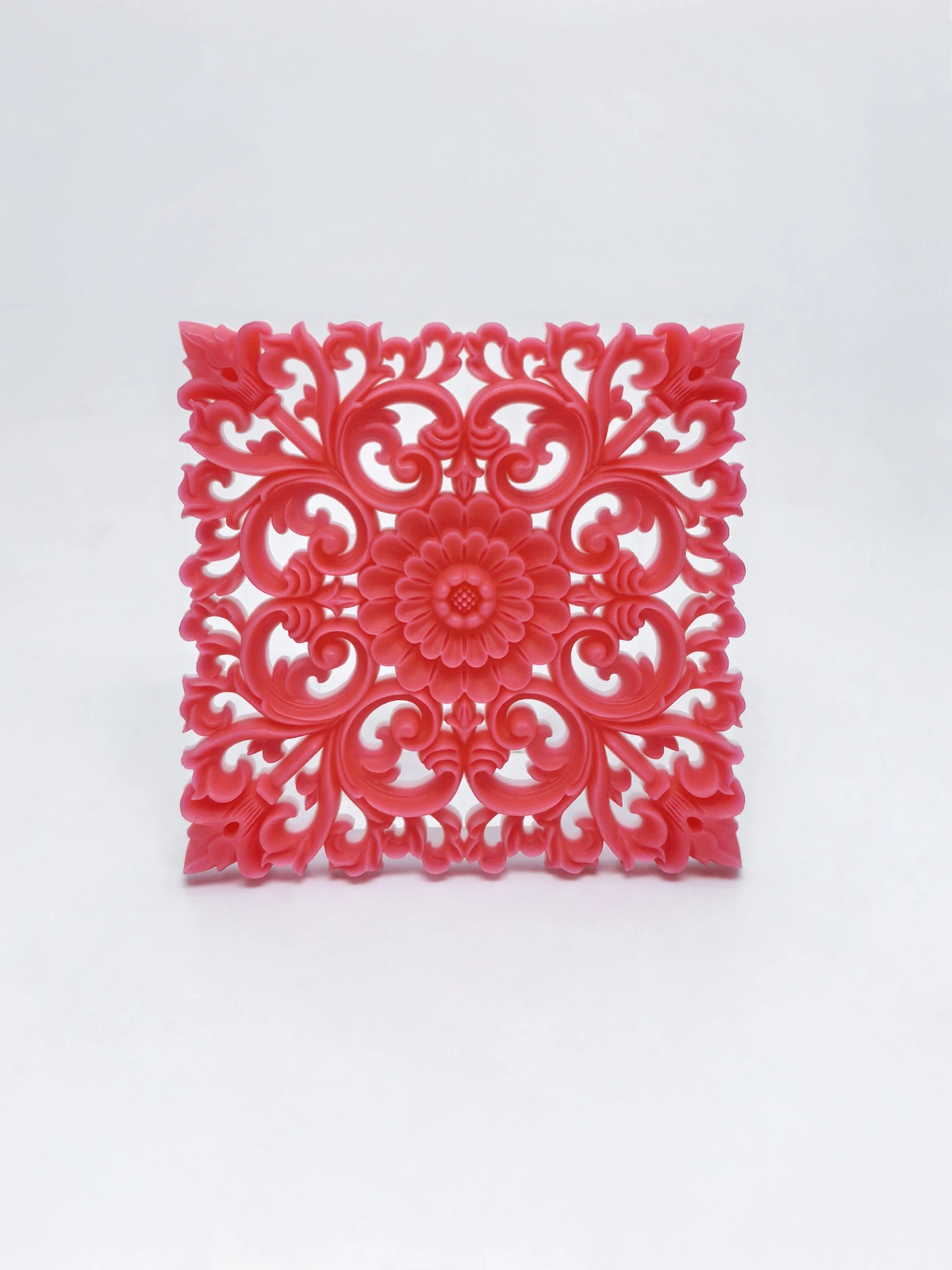
Through-holes, shallow relief, fine mesh and enclosed cavities need separate consideration. A through-hole connects two sides; shallow relief retains a continuous backing; fine mesh relies on several connections to hold its shape; an enclosed cavity creates an interior that cannot be reached directly. All may look light in a rendering, but present different manufacturing questions.
Mark the thinnest connections, longest spans, narrowest openings and transitions between thick and thin areas in CAD. Then inspect the front, back and local sections. A rib or setting can obstruct a hole that looks open from the front, while a generous entrance can narrow inside.
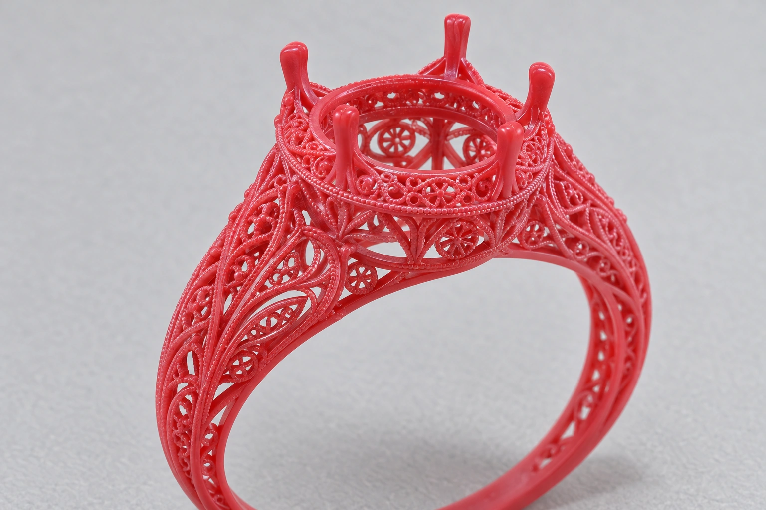
Consider an openwork ring shank. A wire joining two nearby borders and a wire passing several openings before returning to the body can have the same thickness yet very different handling and cleaning conditions. Minimum wire diameter alone cannot describe the pattern’s manufacturability. Review length, bends, neighboring connections and position together.
Describe the actual production method accurately when cast jewelry has a filigree appearance. Casting a printed wax pattern produces fine mesh through a different process from traditional handmade filigree; product descriptions should preserve that distinction.
2 Fine connections must survive cleaning and handling
When a wax pattern leaves the printer, surrounding support may still hold its fine features. After cleaning, the wires must maintain their shape through their own connections. Picking up, storing and attaching the pattern to a tree introduce further contact. Alongside the printed shape, decide where the pattern can be supported and lifted.
Pattern handling resistance is also a concern for wax-material suppliers. 3D Systems’ description of VisiJet Wax Jewel Red specifically discusses handling lightweight filigree and fine-mesh patterns through the lost-wax process. That performance belongs to its specified material system; establish structural limits for Cprint 3D equipment and materials with appropriate samples.
For areas prone to bending or breaking, compare shorter spans, relocated connections or a continuous border. Review appearance, weight and finishing access at the same time. An added connection can make the structure more continuous, for example, while narrowing openings and changing the pattern’s negative space.
If temporary protective structures are used, decide when and how they will be removed and whether the attachment marks can be finished. Members retained through the metal stage will also need cutting and dressing, so assess tool access.

3 Build cleaning access into the model
Check complex openwork with three questions: can the cleaning medium reach the area, can removed support material leave it, and can the result be inspected? Consider entrances, internal turns and exits as one route. A clean exterior does not establish that the interior is clean.
A basket beneath a setting may look open from the side, while overlapping layers obscure internal connections. Designers can inspect the route in section; production staff can then assess it against the actual equipment, materials and operating procedure. Adjust openings, connections or part divisions where needed and confirm the resulting appearance.
Enclosed cavities require separate solutions for removing internal material and forming the casting mold. Discuss process openings, cores or assembly from separate parts with the caster. A cavity in CAD does not by itself resolve cleaning the print or producing the final hollow metal structure.
Cleaning must protect the build wax. Follow the equipment and material procedures for temperature, medium, time and handling; validate risky areas on new designs before processing complete patterns. Support removal clears the temporary printing material, whereas subsequent dewaxing removes the pattern wax during mold preparation. These are distinct operations.
4 Design printing supports and casting sprues separately
Printing supports temporarily hold features during printing; casting sprues provide paths for metal to enter the mold cavity. Identify the function of every added member and the stage through which it remains.
Formlabs’ jewelry-pattern casting guide states, for its resin workflow, that automatically added software supports should not simply become sprues. Purpose-designed printed sprues can also provide support in some filigree structures. The functions therefore need separate assessment. The guide’s resin dimensions and processing parameters do not directly apply to wax systems.
For fine mesh and interwoven patterns, the caster must consider the alloy, overall geometry and casting conditions to determine metal entry, feed locations and removal of the connections. A convenient tree-attachment point may be close to a feature that must remain intact; a less visible location may be harder to dress afterward.
If some sprues will be printed together with the wax pattern, identify their role in the model and confirm connection, inspection and removal requirements. Review both feeding and finishing access to decide whether the arrangement suits the complete design.
5 Compare the same feature at each stage
When wires break, holes become blocked or detail becomes shallow on the finished piece, locate the earliest record showing the change. Compare the same feature in the same model revision across CAD, the cleaned wax pattern, the as-cast metal and the finished piece to narrow the investigation.
| Inspection stage | What to record | What to check first |
|---|---|---|
| File export and print preparation | Missing features, closed openings, visibly faceted surfaces | Differences between the source model, export and processed file |
| After support removal | Broken wires, distortion, residue in openings | Formation, cleaning and handling records |
| As-cast metal | Missing areas, blocked openings or surface anomalies | Pattern handover, investment or shell building, burnout and pouring records |
| After dressing or polishing | Rounded edges, shallow detail, locally worn-through areas | Work locations, tool access and surface requirements |
The time a problem is discovered is only a clue. A broken wire seen after support removal still needs earlier observations and operating records to distinguish incomplete formation from cleaning or handling damage. If the as-cast pattern is intact and becomes shallow only after polishing, focus on finishing.
Keep viewpoint, scale and lighting as consistent as practical in comparison photographs, and mark the same inspection feature. Different angles and magnifications affect visibility; do not interpret photographic differences as geometric change.
6 Validate the complete design with local samples
For a new complex design, choose risk areas such as long slender connections, tight turns, small openings or recessed textures for local samples. Retain the real connections, orientation and surrounding structure as far as possible so that the inspection resembles the actual design.
To compare modifications, keep the surroundings the same and change one main feature at a time, such as connection position or opening size. Record design values, print materials and conditions, and corresponding results after cleaning, casting and finishing. This shows which problem the change addressed.
After a local sample passes, make the complete design. Handling positions, cleaning routes and metal feeding can differ from those of the sample. Success in one local feature does not establish a universal minimum dimension for every pattern.
Define detail-retention criteria before acceptance: which holes must remain open, which edges must remain crisp, where dressing is allowed and how the surface is checked. Application engineers and casters should choose size variants for the actual task. Assess wearing strength and connection reliability separately against the final metal, structure and intended use.
For a new openwork design, give production staff the complete CAD, critical areas, intended alloy and surface requirements. Mark wires and openings that must remain. Plan sample validation around those locations to provide a clear basis for design changes.
Frequently asked questions
Does printable openwork always cast completely?
Cleaning access, pattern handover, mold formation and metal filling still need confirmation. Printing is one stage; check whether the detail survives into the as-cast and finished parts.
How fine can openwork jewelry be?
Consider the specific equipment, material, wire length, connections, orientation and later operations. Supply the complete local geometry and state whether acceptance concerns the wax pattern, as-cast metal or finished jewelry. Confirm it with a corresponding sample.
Does shallow detail on the finished piece mean poor printing accuracy?
First compare the cleaned wax pattern and the as-cast metal. Detail can change during file processing, printing, cleaning, casting or finishing. Records from each stage help identify where to investigate next.