

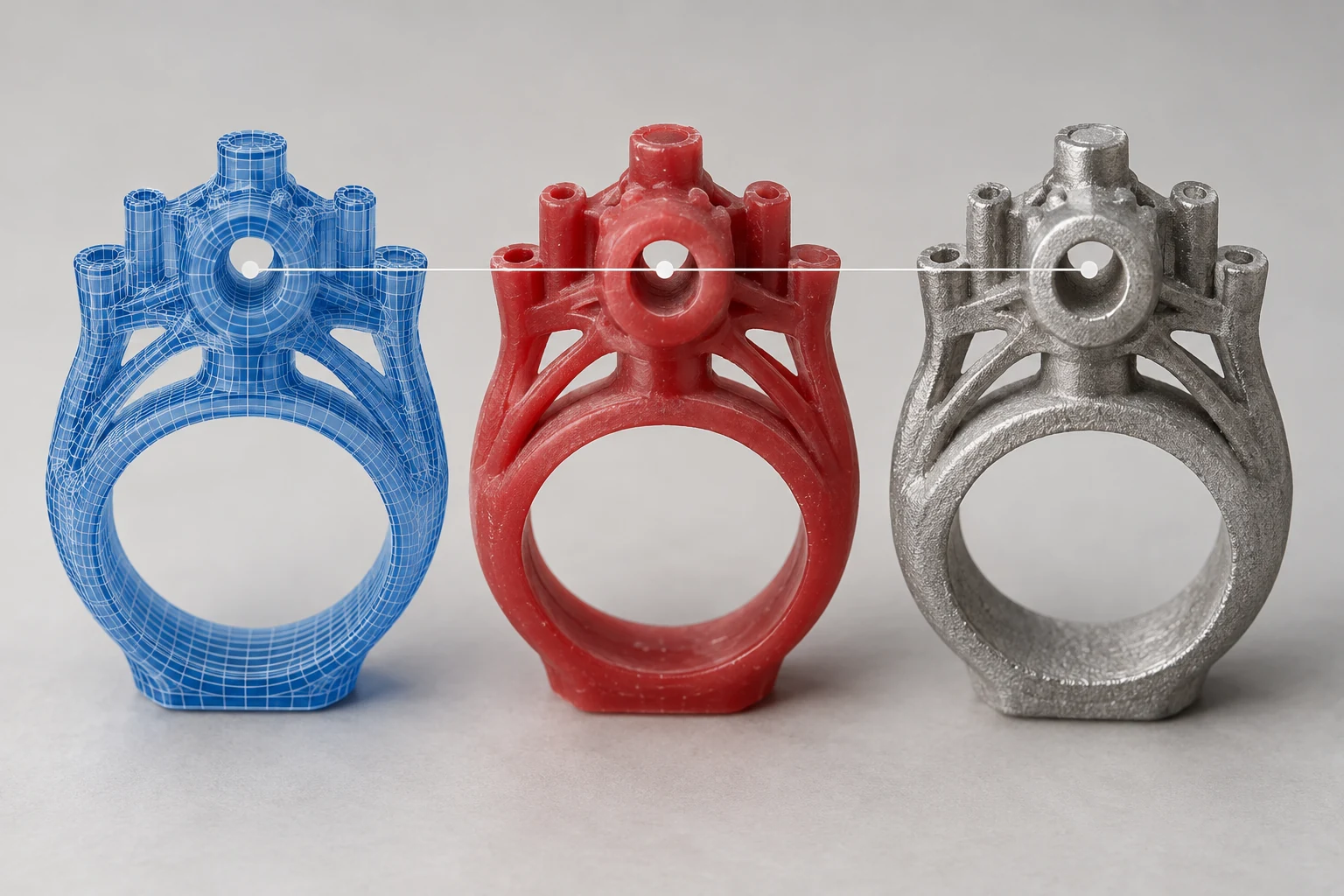
A wax pattern can pass dimensional inspection while the metal casting still falls outside its requirements. The pattern is one stage in a chain of dimensional transfer. The digital file, print job, cleaned model, casting mold, as-cast blank and machined part represent different geometric states and inspection objects.
Trace the same feature through those stages to establish where a deviation was first observed before discussing compensation or process changes. Comparing only the final casting with the on-screen model can mix file units, measurement datums, machining allowances and material changes into a single unexplained problem.
Define What Passing Inspection Actually Means
The size on a finished picture may not be the size that the wax model should be. The designer may have made machining allowances, the foundry may require confirmed compensation geometry, or the print job may use a separate build. If these adjustments are not recorded, the measurement results lack a clear reference.
It is recommended to keep the finished product drawing, the as-cast blank drawing and the approved wax pattern document at the same time. If the project does not have an independent rough drawing for the time being, it should also be stated in the dimension table which features are inspected as cast and which features rely on subsequent processing to meet the requirements.
“Wax-up qualified” should be specifically written as: a certain version of the model, measured using the specified method under the agreed state, meets the dimensional requirements at this stage. This conclusion does not automatically prove that the casting conforms to the finished drawing, nor does it replace subsequent inspection.
For example, for an installation hole to be processed, what needs to be confirmed in the wax pattern stage is the approved rough hole shape or the corresponding reserved structure. The final fitting hole diameter may be obtained by machining. Evaluating both with the same target value will cause the margin that was originally intentionally reserved to be regarded as a printing deviation.
Jewelry readers can combine The production process of a 3D printed ring to distinguish the inspection objects of the ring circumference, setting, wax model and final finished piece.
Dimensions Must Be Preserved During File Handover
The original model in the design software, the exported mesh file and the model imported into the construction software should check the units and key dimensions respectively. Especially when handing over cross-software, it is not appropriate to release the model just because it looks normal in size.
Rhino’s STL description states that the export will convert the surface to a polygonal mesh, and provides options related to units, import scaling, and mesh tolerance. The actual handover should check the software and documents used, rather than generally assuming that all STL can automatically and correctly transfer units. Rhino STL import and export instructions
You can select the overall dimensions, hole spacing and a key local feature to compare before and after exporting. If the overall shape of the model changes proportionally, the units and scaling should be checked first; if the shape is consistent but local details of the surface change, the meshing and repair records need to be checked.
Any scaling or compensation operations in the build software should also have an approved basis. You can’t have the designer, the print operator, and the casting crew each “touch up a little bit,” and no one ends up knowing how much adjustment was actually used.
Fix the Pattern State and Measurement Method
The state of the wax pattern itself needs to be clarified. Models with supports, models that have just been cleaned, and models that have been tree-assembled may have different measurable positions and clamping conditions. For thin walls, long rods and thin claws, measuring contact patterns is particularly worth confirming.
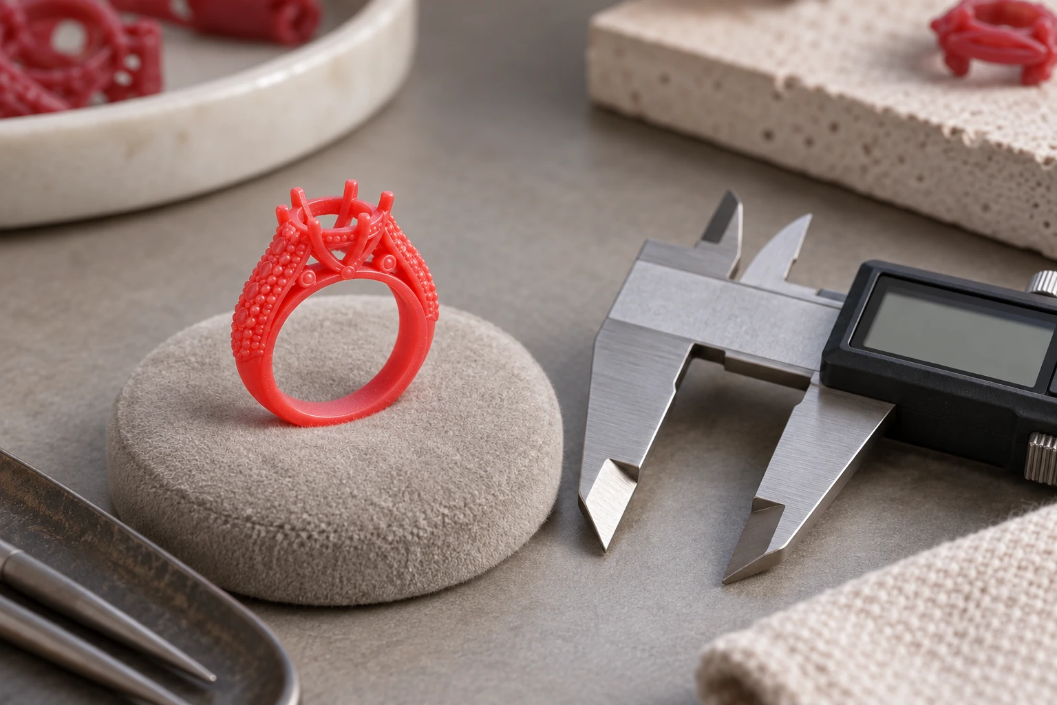
The measuring tool force, measurement direction, support method and environmental conditions should all be compatible with the model. If contact measurements may deform the structure, alternative methods may be discussed with the inspector. You cannot get a “stable reading” by clamping the model hard and mistaking the changes introduced by the measurement for the original dimensions.
The benchmarks for the same feature should also be consistent. Any two points on the curved surface, the maximum outer diameter and the diameter of the section defined in the drawing are different measurement objects. The recording should be accompanied by a location map or cross-section mark so that the next person can reproduce the measurement location.
Review suspicious readings first before determining whether the model is biased. When changing measuring tools, changing measuring people, or changing clamping methods to obtain different results, the measurement consistency should be resolved first instead of adjusting the printed file immediately.
Dimensional Transfer Continues Through the Mold and Metal
The wax pattern geometry is transferred to the casting cavity, and then the blank is formed by metal pouring and cooling. Each stage is subject to different material and process conditions, and dimensional changes cannot be summarized by a uniform percentage.
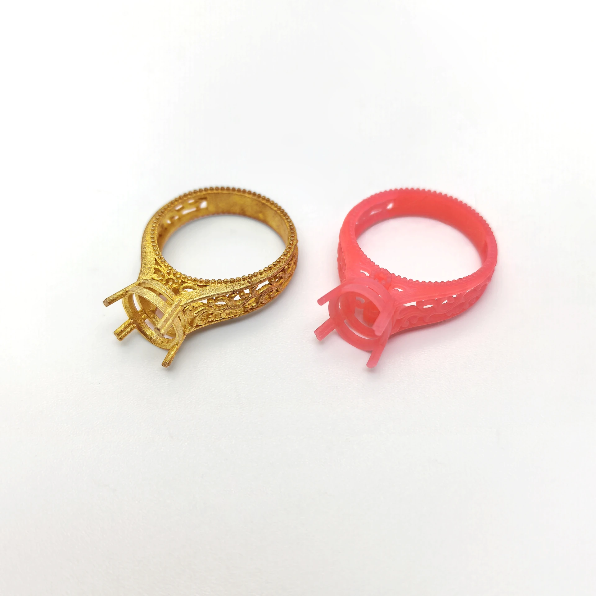
Oak Ridge National Laboratory’s research on investment casting size prediction examines wax patterns, shell patterns and alloys. This study focuses on specific materials and test systems and cannot be used as a universal shrinkage rate for all projects, but it illustrates that dimensional analysis needs to cover multiple stages. ORNL Investment Casting Dimensional Research Summary
When the casting party evaluates dimensions, they also need to know the wax material, mold material, alloy, part structure and actual process records. Whether the compensation plan established for a certain sample is applicable to another thickness relationship or another alloy should be confirmed separately.
If local warping has already occurred during the wax pattern stage, subsequent dimensional deviations cannot simply be attributed to metal shrinkage. On the other hand, even if the wax pattern inspection passes, all casting deviations cannot be attributed to insufficient accuracy of the printing equipment. Each hypothesis should be matched with verifiable evidence along the record.
Machining Allowance and Shrinkage Compensation Serve Different Purposes
The machining allowance is the geometry set aside for subsequent removal of material. Shrinkage or other process compensation is an adjustment to the geometry of the previous stage in order to achieve the goal of a certain stage. Both may exist at the same time, but cannot be mixed together as “amplified model”.
The margin should be stated on which sides, on which basis and for what kind of subsequent processing. Compensation should describe applicable materials, construction, orientation and verification conditions. Scaling the entire part uniformly may not be able to handle local deformations or deviations that only occur on a certain feature.
For the parts to be processed, the size target of the blank also includes whether a processing benchmark can be established, whether there is sufficient margin, and the relevant positional relationship. If the rough part is larger than the finished product, it does not necessarily mean it is unqualified. The key lies in whether it meets the approved rough requirements.
Compensation liability should be determined before trial production. It is recommended that the relevant design and process personnel confirm the adjustment plan, the printing personnel record the execution version, and the inspection personnel evaluate the results according to the stage goals corresponding to the version.
Record the Same Feature Through the Dimensional Chain
| Features | Numerical goals and benchmarks | Wax-up after cleaning | As cast blank | Processed finished products | Changes that require explanation |
|---|---|---|---|---|---|
| Mounting holes or inserts | File version, section location | methods and status | Rough target and actual measurement | Final goal and actual measurement | Whether to follow-up processing |
| Hole spacing or connection location | Same set of benchmarks | Numbering and actual measurement | Corresponding number and actual measurement | Corresponding number and actual measurement | Base conversion relationship |
| outer contour | Specify a section or comparison method | Corresponding location results | Corresponding location results | Corresponding location results | local shape changes |
| Thin walls or details | Key area identification | Completeness and size | Forming status and dimensions | final state | Cleaning and trimming effects |
This is a record structure, not a preset test result. Actual projects should be filled in with real data, units and measurement methods; the reasons for inapplicable stages should be explained, and figures should not be made up to make the form complete.
The same model can be kept related using photos, location schematics, or other traceability methods. Multiple parts of the same style should be numbered separately to avoid matching the results of one wax pattern with another casting into a size chain.
When the same feature is defined using comparable benchmarks and measurements, a difference column of “actual measurement at this stage minus actual measurement at the previous stage” can be added. First find out where the change occurred between the two inspections, and then analyze the reason; the difference only describes the observation results and is not directly equal to the shrinkage rate of a certain material.
Classify the Deviation Before Planning a Test
Overall proportion deviation, fixed direction offset and local warpage require different troubleshooting ideas. If the overall proportion is abnormal, first review the unit and scaling; for local changes, first check the model, clamping and corresponding processes; for changes in different batches, compare materials, tasks and process records.
You can first compare different features of the same model, and then compare multiple items from the same batch and different batches. This way you can see whether the problem is concentrated in a certain structure, a certain location or a certain stage. When the sample size is small, the results are suitable for helping to locate the problem, but it is not appropriate to directly declare that a process capability conclusion has been obtained.
Trial production changes should clearly state the objectives and control conditions. For example, only the approved local geometry should be adjusted while keeping other conditions comparable and checking the corresponding features of the wax model, blank and finished product. If the material, tree shape and processing reference are changed at the same time, these changes should be recorded to avoid attributing the results to a single factor.
Use One Hole to Trace the Investigation
If the hole of a certain part does not meet the requirements in the finished product inspection, you can first check the cross section and measurement method defined in the finished product drawing, and then check the processing records and blank status. If the rough hole is intended for subsequent processing, it should be evaluated according to the rough requirements rather than directly compared with the finished hole diameter.
Then find the corresponding wax pattern and check how the hole appears on the approval document and the cleaned model. If the digital file is inconsistent with the wax model, the export, construction and measurement should be checked; if the wax model meets the stage goals but the blank is different, then evaluate it based on the casting records. Each step corresponds to the same hole, so the problem does not jump between different objects.
If it is found that the difference in readings comes from different sections, first unify the measurement locations and check again. If it is confirmed that it is a local hole shape change, record the specific shape and location. It is not appropriate to just write down an average hole diameter. Stage records should use actual measurement results, supplement hole shape and cross-section information when necessary, and avoid summarizing values to cover up local changes.
It is best to keep the original readings and measurement position diagrams for dimensional chain records, and continue to recheck according to the corresponding requirements after adjustments. You cannot just save the compiled conclusions and delete the original results, otherwise it will be difficult to distinguish real changes from changes in statistical or summary methods later.
Frequently Asked Questions
Must the Casting Be Measured When the Wax Pattern Passes?
Needed. They should be inspected according to the acceptance requirements of wax models, blanks and finished products respectively. Passing a certain previous stage can only prove that the specified projects in that stage meet the requirements.
Should Every File Be Enlarged When a Casting Is Undersized?
The target, unit, measurement method and deviation form should be reviewed first, and then the adjustments should be confirmed by the design and process personnel. Local deformation, hole shape changes or processing reference problems may not be solved by unified amplification.