

File checks before wax printing answer two main questions: does the manufacturing file match the approved design, and can its data and geometry be interpreted correctly? These checks do not replace validation of cleaning, casting or final assembly, but they can keep wrong versions, unit errors and unsuitable repairs out of production.
Check identity and scale first, then geometry and critical details, and finally review every repair. Even when software calls a file ‘printable’, the release record should explain why it was accepted.
Start with Version and Units
When receiving files, first check the style, version, production purpose and quantity. Similar styles, different ring circumferences or different text versions cannot be identified by thumbnails. If the file is inconsistent with the task order, the identity issue should be resolved first before grid repair.

Units should be verified by actual dimensions. You can select the overall shape and a key local dimension and compare the results in the original, exported files and build software. It is impossible to judge whether the scale is correct by just looking at how much area the model occupies in the window.
Rhino’s STL documentation explains options for mesh export and import unit handling. When handing over between different software, the actual import results should be examined rather than assuming that unit information must be interpreted consistently. Rhino STL file description
At the same time, check the number and structural relationship of objects. It should be clear which of the ring body, independent accessories and temporary auxiliary structures are manufactured together and which are delivered separately. Orphaned objects without purpose description should not be deleted directly, nor should they be added to tasks without confirmation.
Distinguish Designed Holes from Broken Surface Boundaries
The hollow hole in the jewelry can be a through-structure in the complete solid body, and its surrounding surface can still be closed. Bare edges or openings in the software inspection may indicate that the mesh does not form the expected closed boundaries. Just because they are both called “holes” doesn’t mean they should be treated in the same way.
Before processing, you should check the original manuscript or feature drawing to confirm whether the opening is the design intention. If a pendant’s string hole is filled in after repair, the software may report fewer errors, but the product functionality has changed.
Deep grooves, flakes, and adjacent but unconnected objects also deserve separate inspection. Just because two surfaces are very close does not mean that they have formed a reliable connection; occlusion in the screen may also make the actual gap difficult to identify.
For models that originally require multiple independent parts, they cannot all be merged in order to obtain a closed whole. The boundaries and output of each component should be clearly defined based on the approved manufacturing structure.
What Geometry Diagnostics Should Check
Rhino’s Check document lists mesh diagnostic items such as degenerate surfaces, non-manifold edges, bare edges, repeated surfaces, normal directions, and separated patches. These items can help find data anomalies, but checking with the command does not guarantee that all geometry problems have been eliminated. Rhino Check and Grid Diagnosis Instructions
Physical inspections can build records around these categories. Degenerate surfaces or zero-length edges may need positioning processing; non-manifold connections need to confirm the real structure; repeated surfaces need to be confirmed whether they are left by mistake; normals and separation sheets need to be checked based on the model usage.
Don’t just save a green pass sign. The inspection record should preferably include the location of the problem, how it was handled, the operator, and the processed version. This way, the designer can know what changes have been made to the file, and the printer can confirm which file was used for the final job.
Auto-healing is suitable for helping process data, but cannot determine product structure on its own. Especially when the operation involves sealing holes, merging parts, or reconstructing local surfaces, you should first confirm the design intent and then check the results.
Review Curved-Surface Detail Separately
Arcs, engravings, and bas-reliefs may change their expression after meshing. In the Rhino mesh setting instructions, parameters such as surface distance, angle, and side length will affect mesh generation. When selecting parameters, you should focus on the details and processing needs of the actual model, rather than simply pursuing more faces. Rhino grid setup instructions

The curved surface of the ring, minimal text, patterned corners and thin connections can be listed as key observation locations. Use the same perspective and cross-section to check the model before and after exporting. If only the overall contour is observed at a distance, local detail loss may be ignored.
Larger files do not necessarily mean better manufacturing input. Irrelevant face counts and duplicate data may increase the processing burden, but they cannot make up for the missing design information in the original manuscript. The basis for judgment should be the expression of whether the key geometry meets the requirements.
The display also does not fully represent the actual mesh. Smooth shading may make polygonal outlines appear smooth, and meshes or sections should be viewed if necessary to avoid approving files based solely on renderings.
Compare Every Repair Before and After
The repaired file should be saved as a different version and the original file should be retained. At least review the overall size, key holes and inlays, number of objects, text direction and local connections to confirm that no new changes are introduced in the process.
For example, after filling a non-designed opening, you should check whether the thin walls near it have been filled together; after merging objects, you should check the gaps that originally need to be retained; after unifying normals, you should also confirm the component boundaries and overall shape.
Documents involving multiple issues can be processed and recorded step by step. If the range of changes in an automatic repair is large and it cannot be confirmed whether it still conforms to the original, the work should be returned to the designer or an explainable repair solution should be used instead.
When releasing, the repair conclusion should state “what was repaired and which reviews it passed”, not just “repaired”. Without saving the review basis, it will be difficult to determine whether the anomaly originated from the original design or the repair process.
Assign Responsibility by Issue Type
| Question Category | Common symptoms | Next step |
|---|---|---|
| Data error | Wrong units, duplicate faces, unexpected bare edges, or damaged objects | Handled and reviewed by appropriate personnel |
| Unclear design intent | Orphaned parts, openings with unknown purpose, versions inconsistent with drawings | Confirm control requirements by designer |
| Process needs to be verified | Delicate details, difficult-to-clean areas, complex connections or internal cavities | Hand over to process evaluation and representative trial production |
The purpose of classification is to prevent all problems from being automatically repaired, and to prevent printing teams from silently deciding geometry for designers. A document may contain three types of questions at the same time, and the conclusions should be listed separately.
Process risks can be recorded as “to be verified”, but the verification conditions must be stated. If it will affect the delivery of this round, you should first determine whether this round is only for trial production; you cannot mark it as unconfirmed and release it according to the stable production document.
Release One Clearly Identified Final File
| Check items | Record content |
|---|---|
| File identity | Style, purpose, approved version and source |
| scale | Unit, shape and key dimension verification results |
| object structure | Number of parts, connections and temporary structures |
| Data diagnosis | Check tools, problem location and processing records |
| key details | Via, Text, Inlay and Surface Review |
| Repair review | Corresponding differences between the original file and the repaired version |
| final mission | Post-import verification, build version and confirmer |
Documents should remain in clear version after release. If the subsequent typesetting software performs operations that will change the geometry, the relevant items should be checked again. Rather than a one-time stamp, document checks are performed around the input that actually goes into manufacturing.
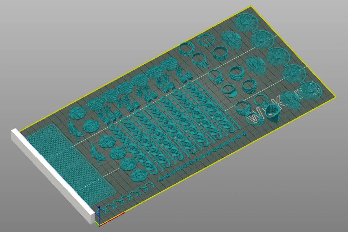
Duplicate styles also need to be checked against this document. A re-exported model may use different mesh settings; a modification of the perimeter may also affect connections or text positions. There is no need to redo all historical research, but examine inputs and associated features that have changed this round.
The final check can retain the overall view, key parts and necessary section views, and compare the modified area with the unchanged datum. “Software diagnosis passed”, “design intent confirmed” and “manufacturing review completed” are recorded separately, making it easy to see the data problems that have been solved in this round, as well as the questions that still need to be answered in trial production.
Reviewing a Hole-Filling Operation
Assuming that the diagnosis reveals an opening on the back, first check with the original to confirm that it is not the designed channel, and then decide to repair it. After processing, not only check whether the boundaries are closed, but also whether nearby thin walls, back contours, and adjacent holes have changed.
If automatic filling turns a curved area into a flat surface, or fills in the adjacent assembly space at the same time, even if the diagnosis is passed, it cannot be used as an approval document. Changes should be explained and a more appropriate treatment should be selected, and if necessary, return to the original design for modification.
The final record can indicate the location of the opening, the basis for verification, the repair method and the review characteristics. Such a conclusion allows the downstream to know what requirements are maintained by the software processing, which is more supportive of file release than leaving only “repair successful”, and also makes it easier to distinguish the original design from the changes introduced by the repair in the future.
The review record should lead back to the final submission, not just the original manuscript. The approved version can be archived with the task list to ensure that subsequent personnel do not misuse a document that has been passed but has been replaced by a new version.
Frequently Asked Questions
Does a Closed Mesh Guarantee Printability and Castability?
A closed mesh only illustrates certain types of data conditions and does not prove that the model is easy to clean, can be molded, or will meet final dimensions. Corresponding manufacturing judgment and verification are also required.
Can an Automatically Repaired File Be Released Without Review?
Dimensions, components and critical details should first be checked against the approved design. The disappearance of the error and the correct retention of the design are two results that need to be confirmed separately.