

Before jewelry CAD becomes a wax pattern, the design intent must become a print job that can be executed and inspected. Opening the file completes only part of the handover. Confirm the design version, ring size, stone information, critical details and downstream casting requirements alongside the model.
Preparation should give designers, printing teams and downstream makers one approved version, with clear boundaries between adjustable and protected features. The print then has a defined acceptance reference, and later changes can be traced to their reasons.
Freeze the Design Intent and Critical Requirements
Before starting to prepare documents, you should confirm the purpose of this round of production. Wax-ups used for appearance display, wax patterns used for casting trials, and repeat production models of stable styles may have different inspection priorities. Not all requirements can be determined based on the same rendering.
The ring should describe the ring girth system, measurement method and inner ring shape; the style that needs to be set should provide the relevant size of the actual gemstone or the confirmed stone matching plan. Inserts, claws, assembly connections and wearing contact surfaces should be marked in the drawing to avoid just “do as the drawing does” handover.
GIA’s jewelry CAD/CAM instruction connects design, proportion and manufacturing. Digital modeling is not a pure expression of appearance, and this production-related information needs to be retained when preparing production files. GIA Jewelry CAD/CAM Course Introduction
Design validation should also indicate what has not yet been determined. If the actual stones are not in place, the model can only be made according to the currently approved conditions, and the tentative dimensions should not be taken as a guarantee of the final setting. Clear open items can help the team decide whether to verify the appearance or continue production preparations this round.
Native Design Files and Print Files Serve Different Purposes
Original CAD files are suitable for retaining editable design structures, objects and modeling information. The grid file used for printing needs to comply with the format and requirements supported by the actual device software. Both should be filed separately, and a single repaired grid cannot be used to overwrite the unique original.
The file name should include the style or project, version and purpose. When revising, keep a description of the changes, such as adjusting the ring circumference, modifying the setting, or changing the connection position. Just using names like “final” and “latest final” doesn’t tell you which version was approved.
Before exporting, the handover unit must be determined and key dimensions selected for verification. For complex styles, it should also be stated whether it is a complete model, multiple separate parts, or whether it includes temporary auxiliary structures. The receiver should not have to guess at which objects to print together.
If the drawings and models are inconsistent, the control basis should be confirmed by the designer first. Printers should not change one copy to another to “look similar” on their own, otherwise subsequent inspections will not be able to determine which set of design requirements was adopted.
Mesh Export Changes How Geometry Is Represented
Mesh files such as STL express shapes through polygons. Rhino’s STL description states that the surface model needs to be meshed when exported, and the degree of approximation can be controlled through related settings. Surface originals and exported meshes are not exactly the same data form. Rhino STL description

After exporting, arcs, thin characters, hollow edges and small connection structures should be reviewed. A mesh that is too coarse may change the appearance of the surface, and large file sizes do not automatically represent correct details. Inspections should be centered around the most sensitive features in the model, rather than just pursuing file size.
Verification methods can include key dimensions, partial enlargement, and cross-section comparison with the original model. For easily confused embossed characters, the direction and depth of the characters should be confirmed. If there is one component missing after export, or there are more test modeling objects, it needs to be processed before entering printing and typesetting.
After importing the construction software, the unit, shape and number of parts should be checked again. Just because a file was correct in the previous software does not prove it is still correct after importing, scaling or repairing. Every operation that changes geometry should have a traceable version.
Geometry Diagnostics Do Not Replace Manufacturing Judgment
Software can help check for data issues, but it cannot automatically understand stone fit, wearing comfort and subsequent finishing requirements. Rhino’s Check command is used to report errors in object data structures, and its documentation also explains that passing the check does not mean that all geometric problems have been eliminated. Rhino Geometry Check Instructions
Problems discovered before printing can be divided into three categories: data errors, unclear design intentions, and process needs verification. Data errors should be repaired and reviewed by the corresponding personnel; unclear design intentions should be confirmed by the designer; whether the structure can withstand cleaning and casting requires process evaluation or representative trial production.
For example, an isolated small piece may be an object left by mistake, or it may be an accessory that needs to be manufactured separately. The purpose should be confirmed before automatic deletion. A through-cut hole may be a design feature and should not be filled in just because the software prompts “there is a hole”.
Diagnostic records should retain differences before and after treatment. Especially for repairs involving text, thin walls, connections and inlays, it is necessary to check whether the repair has changed the original requirements, not just to observe whether the number of errors has been reduced.
Discuss Handling Before Build Layout
Print poses, support areas, and post-processing operations may affect model contact and inspection locations. Designers mark out the details that must be protected, and printing teams evaluate whether they are easy to handle when forming, cleaning, and handling.
For subsequent models that require tree assembly, you should also know in advance where sprues are allowed to be connected. Who designed the sprue, whether it will be printed with the model, and which structures will be cut off later should be stated in the task file. Printed supports cannot be treated as sprues without confirmation.
Whether weak parts need to be modified should be determined through design and process communication. Printers can raise risks, but they should not silently thicken patterns, fill in hollows, or move borders. Even if adjustments make the operation easier, they may change the style and final production requirements.
If it is not possible to judge at the moment, you can select samples that represent key structures for trial production and clarify what will be verified in this round. Don’t let “print it first” become a goalless endeavor; at least know what details to check and what results will trigger a redesign.

Record the Preparation in a Job Sheet
| Task items | What needs to be confirmed in this round |
|---|---|
| Production purpose | Appearance confirmation, casting trial production or repeated production |
| File identity | Version correspondence of original manuscripts, exported files, and build tasks |
| Key requirements | Ring circumference, setting, connection, appearance and inspection position |
| Geometry changes | Approval records for allowances, compensation, repairs and temporary structures |
| print arrangement | Quantity, posture, identification method and protection area |
| delivery status | Delivered with supports, cleaned or assembled |
| Acceptance basis | Target size, inspection method and exception feedback person |
The task order does not need to be long, but it must be able to answer “which version is printed this time, why is it printed like this, and how to judge whether it is passed.” For projects that require the participation of multiple people, it should also be determined who has the authority to approve geometric changes to avoid multiple links adjusting the same model separately.
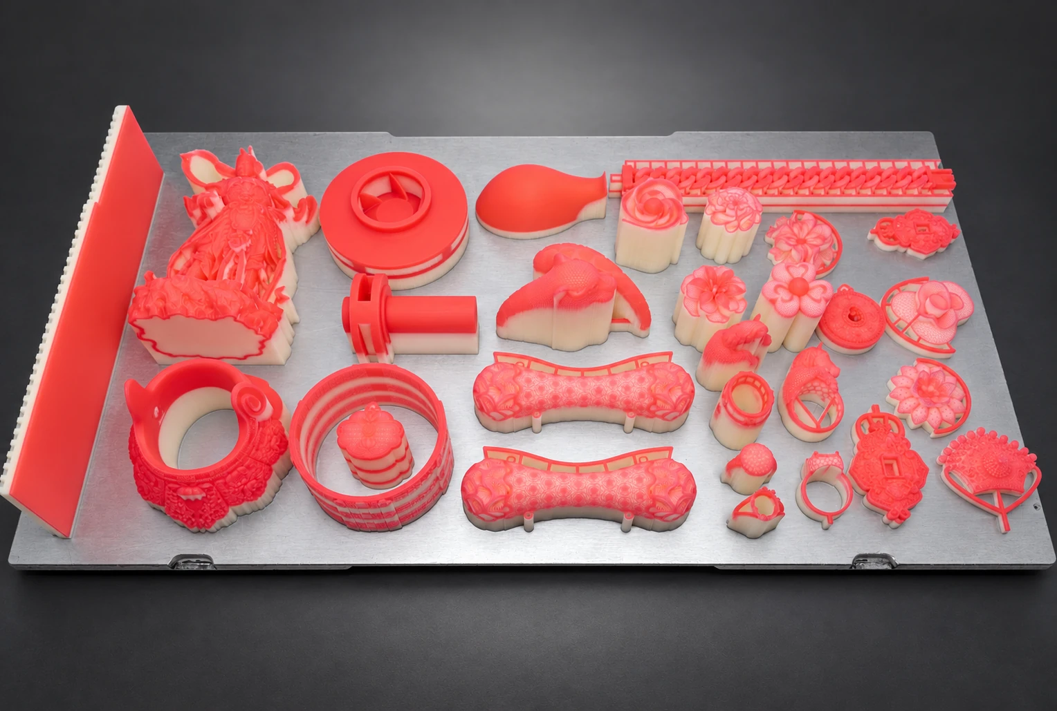
Screenshots of typesetting confirmation can be used as task attachments and cannot replace the actual build files. If the direction, quantity or location is changed later, the new task version should be saved, and the receiving personnel should also know which file to use for this round.
When preparing tasks for Cprint 3D equipment, you can check the input and construction requirements with the product data of 3H-420 Plus wax model 3D printer.
Create a Reusable Production Handover
It is recommended to archive six categories of content: original design files with access rights, approved export files, key feature diagrams, change records, approved build tasks, and inspection results. They describe the design origin, manufacturing input, retention requirements, reasons for adjustments, actual execution, and output status respectively.
In repeated orders, first check whether the current demand is still consistent with the archived version. Changes in ring circumference, replacement of gemstones and local style modifications may affect the original manufacturing preparations. Even if only one parameter is changed, check whether the associated characteristics have changed.
For long-term reuse styles, records can help the team distinguish design revisions from process adjustments. This way, the next time something goes wrong, you can go back to the correct original, rather than working through multiple meshes from unknown sources.
A design modification should form a set of corresponding updates: modification instructions, approved design version, re-exported mesh, and this build task. Old construction tasks are retained for traceability, and new tasks recheck key dimensions and quantities to avoid that the design file has been updated and the printing end still uses the last layout.
Handing Over a Ring-Size Change
Assuming that the customer adjusts the ring circumference based on the original model, the designer first saves the new version and explains the changed area. Then check whether the inlays, text, patterns and connections still meet the requirements, and then output the corresponding grid.
A before-and-after picture can be attached to the handover: where has the inner circle changed, which features need to be retained, and which content needs to be re-confirmed. The printer prepares the job according to the new version and checks the quantity and delivery status at the same time. They should not just do unrecorded scaling in the old build file.
If the setting still needs to wait for confirmation of the actual stone, the task order should be limited to this round of inspection. Wax-ups can be used for current geometry or appearance discussions, but the recipient should know which is not yet final for fabrication. After the gem information is confirmed, the modifications will be written into the new approved version.
The information for minor modifications does not need to be lengthy. The key is that the files, difference diagrams and task orders correspond to each other. The next time you reuse the model, you will know what kind of ring and stone matching conditions the model belongs to.
If the quantity or delivery status is temporarily changed after the build task is handed over, the task description should also be updated. Just because the geometry has not changed does not mean that the processing, sorting and acceptance arrangements are still the same; relevant personnel need to know the actual execution conditions of this round.
Frequently Asked Questions
Can a CAD Model Go Straight to the Printer?
It is necessary to confirm the format support, file version, unit, geometry and manufacturing requirements before forming a printing task. Being able to import does not mean that preparation has been completed.
Does Wukong Software Design Jewelry Shapes?
Wukong undertakes tasks such as slicing, typesetting, and construction preparation. The creative modeling and design confirmation of jewelry should still be completed in the corresponding design tools and workflows. The handover should differentiate between the original design documents and the actual construction tasks.