
A printed wax pattern must leave a cavity in the casting mold before metal can take its shape. Jewelry investing and industrial ceramic shell building both serve this purpose, but they differ in mold formation, pattern assembly and process control. Choose the route around the part, alloy and material system validated by the foundry, rather than the label “jewelry” or “industrial”.
For designers and printing teams handing over wax patterns, the useful questions are whether the mold material can reach every relevant surface, whether the pattern can retain its shape during mold making, and whether it can later be removed successfully before pouring. Answering these questions in advance reduces rework more effectively than a general request for finer printing.
How the Two Methods Create the Casting Cavity
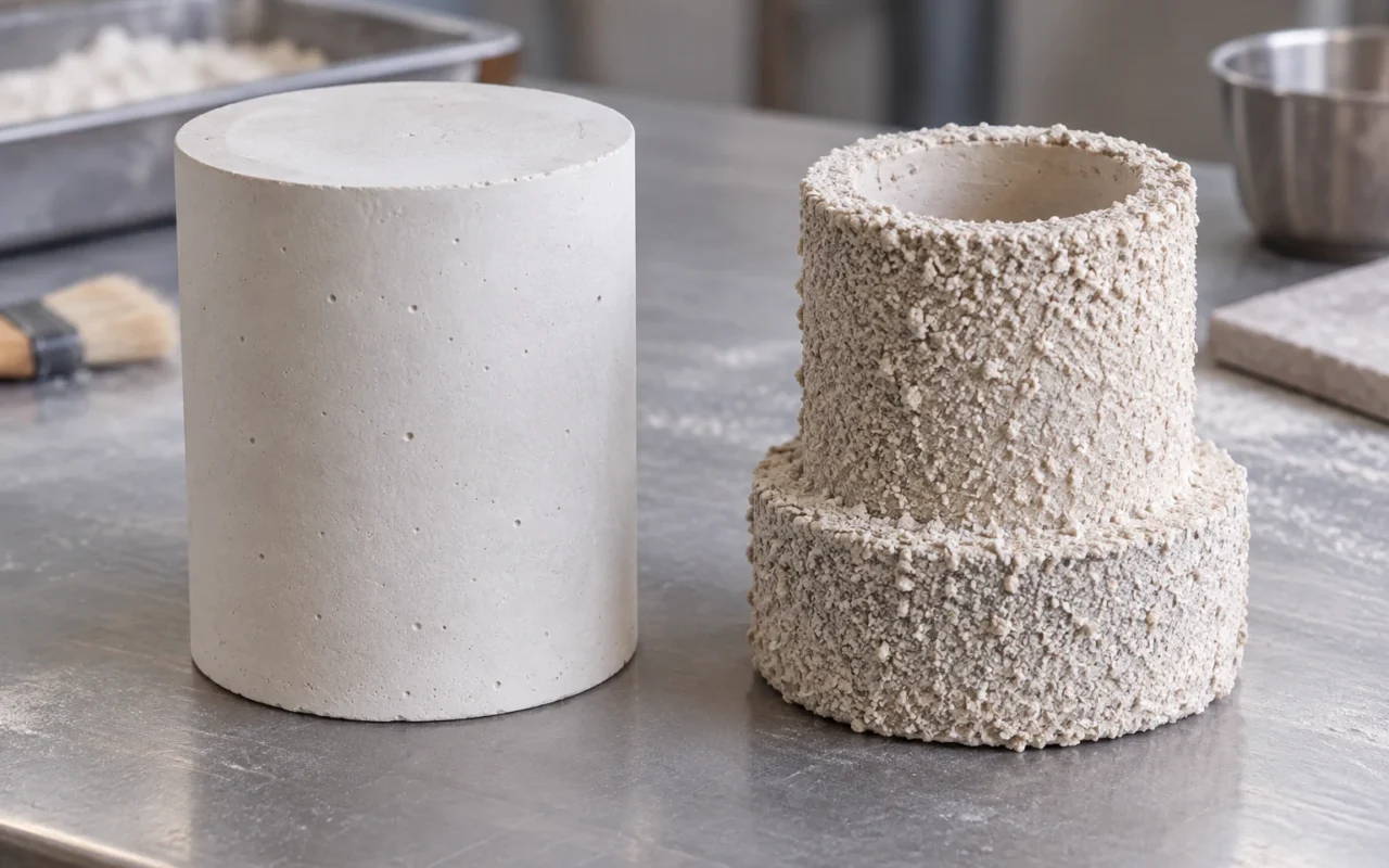
A common jewelry investment process involves putting the assembled wax tree into a container, surrounding the model with the prepared investment slurry, and then entering the appropriate heat treatment and casting process after the material hardens. Ransom & Randolph’s instructions for jewelry craftsmanship show the relationship between tree assembly, investment, heat treatment, pouring and subsequent cleaning. For specific material ratios and operating conditions, the process instructions of the corresponding products should be used. Jewelry investing process description
Ceramic shell building forms a shell layer by layer around the wax tree. The tree is dipped in slurry, coated with refractory grains and dried; these steps are repeated until the shell meets the process requirements. This process coats wax patterns and differs from directly printing sand molds. Investment Casting Institute — Ceramic shell building
Both have a positive form that needs to be retained, which is then removed and the remaining cavity used to pour the metal. Differences also include how the material goes into detail, how the cast gains strength, and how the heat treatment matches the wax.
When you need to put mold formation back into the front and back processes, you can view Wax Pattern Post-processing and Lost Wax Casting Complete Process.
Jewelry and Industry Do Not Define a Fixed Process Boundary
“Jewelry investment” and “industrial shell building” are common terms used to facilitate communication and cannot replace project judgment. Artistic casting may also use different casting systems. For example, the lost-wax department of Pangolin Editions introduced both block investment and ceramic shell processes, indicating that the application names cannot completely separate the two methods. Pangolin Editions Lost Wax Process Introduction
Just because the parts are smaller does not mean that the small inner cavity is necessarily suitable for a certain investment material; the larger appearance does not mean that all problems can be solved by simply thickening the ceramic shell. Deep grooves, narrow passages, partially enclosed spaces and changes in thickness require separate inspection of the entry, exhaust, drying and dewaxing paths of the mold material.
The printing team should describe the actual model to the foundry, not just submit the product assortment. A cross-section drawing with key details is often more useful than “Here’s a jewelry piece.” If the inner cavity requires a core, the core positioning and subsequent cleaning must also be discussed. The printable cavity cannot be directly regarded as the solved casting inner cavity.
Investing: Slurry Access and Setting
When embedding in blocks, there needs to be enough space around the model and between adjacent models for the slurry to enter. Closely spaced cutouts, thin claws, and patterns close to the bottom are all worth checking out in advance. What is “enough” here is determined by the material system, the shape of the model, and the way the foundry operates. A uniform spacing cannot be used to replace all items.
The preparation, mixing method, operable time, bubble control and resting conditions of the investment powder and liquid will also affect the results. The printing team should not change the recipe for the foundry based on other brand tutorials, but it can provide the most difficult to fill positions in the model to help the other party arrange the focus of inspection.
For example, if a pendant has a deep relief and a narrow groove on the back, both front and back sides should be unfolded when confirming the appearance. If you only look at the front rendering, the back may become a blind spot for subsequent communication. After assembling the tree, you should also check whether the slot is blocked by the connecting parts, or whether the adjacent models are too close to be inconvenient to observe.
Pre-embedding wax pattern inspection should occur before material covering. Once the original broken claws, deformations, surface attachments or support residues are covered by the embedding material, the opportunity for direct inspection and disposal is lost. When problems are discovered, they should be reprocessed and re-inspected as agreed, rather than hoping that subsequent heat treatment will eliminate all problems.
Shell Building: Coating Access and Layer-by-Layer Drying
Ceramic shell making requires a slurry and stuccoing process that covers the surface where the cavity is to be formed. The wax tree layout therefore requires space for immersion, draining, stuccoing and inspection. The two models block each other, which may make it difficult for the operator to observe the deep coating.
Model orientation cannot be determined solely by convenience when printing. The posture in printing and typesetting serves for shaping and post-processing; the posture of tree assembly serves for shell making, dewaxing and pouring. They can be different, but you should know the subsequent connection areas and fragile details before printing to avoid inconvenient tree assembly operations after completing the model.
Drying is part of shell making. The number of shell layers, material combinations and drying conditions belong to the foundry’s process system and cannot be inferred from photos. For the design and printing team, it is important to confirm that the model can withstand the agreed handling and processing operations, and whether there are any covered areas that would hinder drying or inspection.
Assuming that there is a visual gap between the two ornaments, you cannot judge the usability of the layout based on this gap alone. The actual operation also needs to consider the clamping tools, movement during grouting, sand spreading direction and spatial changes after the shell is formed. This type of judgment should be made in the tree assembly plan and confirmed by the person responsible for shell making.
Confirm Dewaxing and Burnout with the Mold System
Completion of investment or shell building does not mean that the mold can be poured immediately. Removing wax patterns, treating residues and bringing the mold to a specified state are important steps in the subsequent process. Different systems may use different equipment and arrangements, and one furnace temperature curve found online should not be used for all wax materials and molds.
The heat treatment plan also needs to consider the wax volume, connection and discharge paths, mold structure and material supplier requirements. The same material name does not mean that models of different sizes and structures can directly use all conditions.
When cracks, residues or casting surface abnormalities occur, the problem record should include the mold material used, wax material, assembly status and process batch. Just “it would be better to switch to shell making” or “the embedding powder is not good” cannot explain the reason. The stage at which the abnormality occurs should be confirmed first, and then relevant personnel will propose verification methods based on process records.
Compare Both Routes in One Handover Table
| Compare items | What needs to be explained about block embedding | What needs to be explained about ceramic shells |
|---|---|---|
| Mold formation | Containers and slurry filling and hardening arrangements | Dipping, stuccoing and layer-by-layer drying arrangements |
| Model details | Filling and bubble inspection of deep grooves, thin sections, and adjacent gaps | Cladding accessibility, sheltered areas and local shell inspection |
| wax tree layout | Coordinates with container, slurry entry and subsequent pouring | Compatible with immersing, draining, stuccoing, drying and pouring |
| wax pattern state | Complete, clean, dimensions and connection areas as agreed | Complete, clean, able to withstand agreed operations and easy to cover |
| heat treatment | Confirm with investment materials, wax materials and equipment | Confirm with shell materials, wax materials and equipment |
| Verification results | Check corresponding models, molds and castings | Check corresponding models, shell types and castings |
This form is suitable for asking questions and is not a replacement for process documentation. If one party is unable to answer an item, it should be listed as an item to be confirmed on the project to avoid leaving the printer solely responsible for casting process judgment.
Information to Prepare Before Pattern Handover
It is recommended that geometry files, dimensional drawings, target alloys, finished product surface requirements, and wax material information be submitted to the foundry. The dimensional drawing should distinguish between as-cast requirements and subsequent processing requirements, and the appearance drawing should mark the locations where sprues are allowed to be connected and where key protection is required.
The delivery status should also be stated: whether the model is supported, unsupported, or the wax tree has been assembled. For models that have been tree-assembled, the correspondence between the whole tree photos and numbers should be provided; for models that have not been tree-assembled, it should be agreed before printing who will design the connection locations and who will confirm the final tree assembly plan.
For the first round of trial production, a model that can represent deep grooves, thin walls, and appearance details can be selected, but the conclusions must correspond to the characteristics of actual verification. A sample that passes cannot automatically cover unverified lumens or larger sizes. Only by using this verification to revise the next round of model requirements can reliable handover standards be gradually formed.
The correspondence between the model quantity, serial number and outer packaging should also be confirmed during handover. If a model is a process exploration prototype, the structure to be verified should be clearly defined to avoid mixing it with approved production parts. Both parties can agree on the time and content of the first round of feedback, such as photos of key details, dimensional results and abnormal locations, instead of just receiving a sentence of “cast it”.
What to Recheck When the Mold Route Changes
If a project transitions from block investment to ceramic shell building, wax tree layout, operating space and model delivery requirements should be re-examined. The original arrangement that is convenient for loading into the container may not be equally convenient for soaking and drying. Implement the new plan into the group tree diagram, and then confirm whether the model needs to be adjusted to avoid changing the process name and still using the old conditions for the physical arrangement.
When converting the process, the handover list can be divided into three columns: “remain unchanged”, “needs modification” and “to be verified”. The model identity and finished product requirements are retained, the assembly tree diagram, delivery status and inspection arrangements are reviewed according to the new route, and the first round of trial production is focused on answering unresolved questions. This allows route changes to be implemented into documents and physical objects.
Frequently Asked Questions
Does a Finer Printed Surface Always Make Mold Making Easier?
Superficial appearance is just a condition. Even with a delicate exterior, deep grooves and obscured spaces may still impede material access, inspection or subsequent processing. Geometric accessibility and process arrangements should be reviewed simultaneously.
Can the Printing Team Choose the Mold Route Alone?
The printer can provide wax pattern characteristics, material files and model information. The final casting selection should be confirmed by the project designer and the person responsible for casting based on alloy, structure and verification conditions. After the route is determined, the requirements are implemented into wax-type design and delivery inspection.