

How lost foam casting works
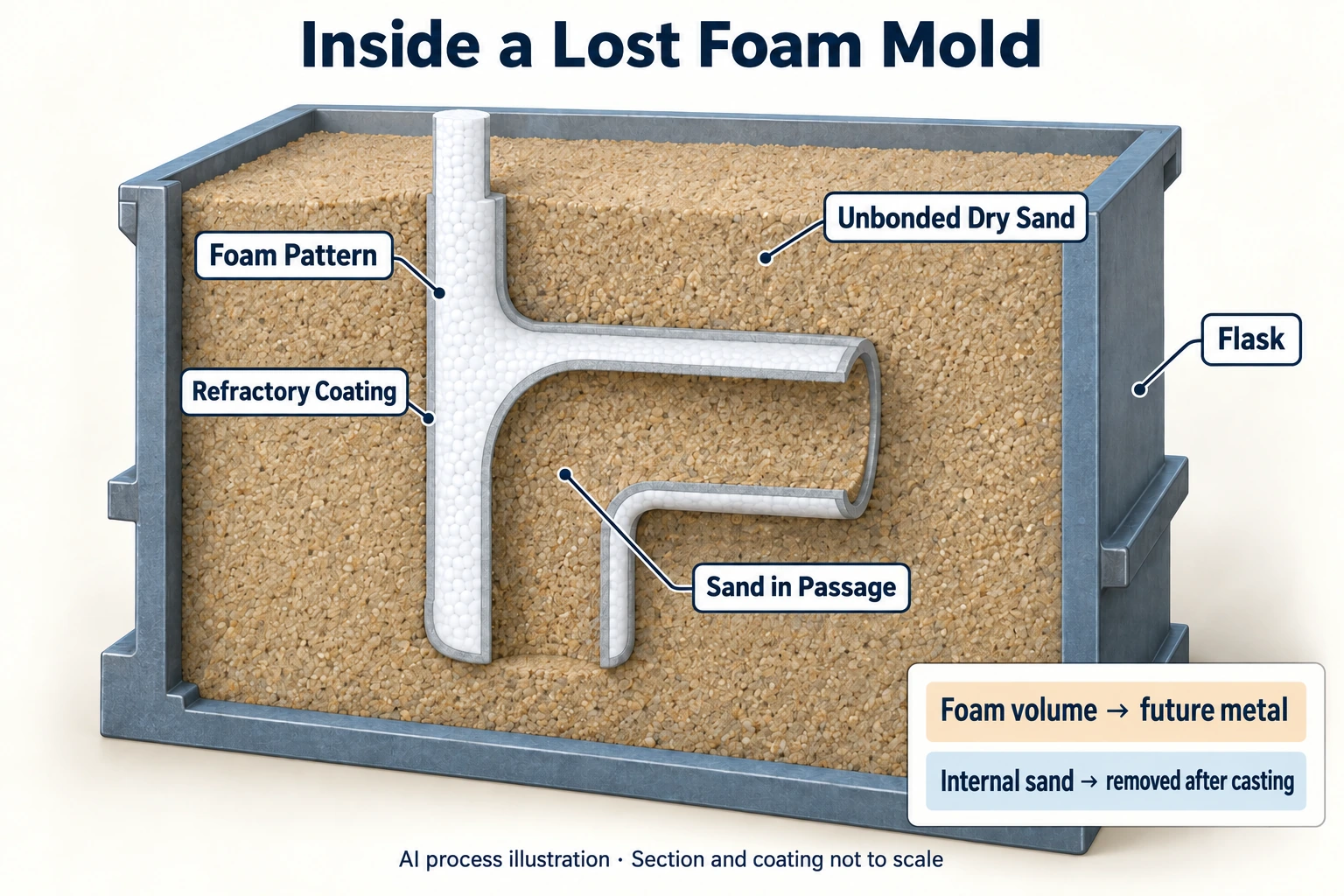
Lost foam casting starts with a foam pattern. The pattern receives a refractory coating, is dried, and is surrounded by dry sand that is compacted by vibration. During pouring, heat decomposes the foam and metal progressively occupies its original volume, forming a casting as it cools. This article covers the common process using a refractory coating and unbonded dry sand.
One feature makes this process easy to distinguish: the foam remains in the sand until pouring. How does the metal enter? Why does the sand not simply collapse into the space as the foam disappears? These two questions explain the process, its design opportunities, and its main quality controls.
1. Understand the foam pattern, coating, dry sand, and flask
The foam pattern represents the volume that metal will occupy. In a housing with a curved passage, for example, the foam represents the metal walls. Space is left in the passage for sand to enter. Making the entire passage from solid foam will not automatically produce a hollow passage after pouring.
Expandable polystyrene (EPS) is a common pattern material; some processes use polymethyl methacrylate (PMMA) or other materials. Their forming and decomposition behavior differs, so the process must match the material. Pattern sections can be glued together and combined with runners and any necessary feeding features to form a cluster.
A refractory coating covers the pattern surface, separating metal from sand while affecting surface quality and the removal of decomposition products. Its function extends well beyond that of decorative paint, and it must be thoroughly dried after application.
Unbonded dry sand fills the surrounding space and accessible internal passages, providing support after vibration compaction. The coating and sand work together to maintain the shape. For curved passages, check both sand access and adequate filling. The flask holds the complete pattern and sand assembly and accommodates loading, compaction, and venting arrangements. Auxiliary equipment such as vacuum systems depends on the production setup. The U.S. Department of Energy process overview explains how these components work together.
2. The eight steps of lost foam casting
The following eight stages describe the production sequence. In a foundry, activities such as metal melting and pattern preparation can run in parallel. The actual sequence depends on the production line and the part requirements.

Step 1: Make the foam pattern and check its dimensions and condition
A common route is to pre-expand beads, stabilize them, and then form them in a mold. The molded pattern is subsequently stabilized and inspected as required by the process. Checks include overall dimensions, thin-wall areas, density, and bead fusion. Pattern dimensions must also account for the relevant casting shrinkage and machining allowance.
An intact foam shape meets only part of the requirements. The pattern defines the geometry but also decomposes during pouring, so its material condition affects subsequent stages. Producing foam patterns in quantity may require dedicated tooling.
Step 2: Assemble the pattern and gating system
A complex housing may consist of several glued pattern sections, connected to runners and any necessary feeding features. Check joint alignment, bond quality, and assembled dimensions to prevent acceptable individual sections from becoming a misaligned assembly.
The cluster layout must support mold filling, feeding, and placement in the flask. Lost foam casting still requires feeding to be considered for the alloy and geometry; risers cannot be eliminated in every case.
Step 3: Apply and dry the refractory coating
After dipping or another specified coating method, dry the pattern and check coating integrity, uniformity, and local buildup. Joints, corners, and internal passages deserve particular attention in relation to the actual geometry.
Coating thickness and permeability must suit the pattern material, alloy, and pouring conditions. Simply adding thickness cannot replace process validation, and no single drying time applies to every part.
Step 4: Position the pattern cluster in the flask
Prepare the flask, place and support the cluster according to the plan, and arrange the pouring inlet. Orientation must also allow subsequent sand filling: a housing may fit inside the flask while its curved passages remain difficult to fill.
Check sand entry paths into internal spaces, pattern spacing, and stability during flask loading, rather than waiting until after pouring to identify unsupported areas.
Step 5: Add and compact the sand
Gradually fill dry sand around the pattern and into accessible internal spaces, using appropriate vibration to establish support. Two checks matter: whether sand reaches the required locations and whether compaction deforms the pattern.
Stronger vibration or a longer cycle does not necessarily improve the result. Weak pattern sections, glued joints, and areas that are difficult to fill must be validated together with the compaction method.
Step 6: Pour metal to progressively replace the foam
Metal enters the gating system and advances toward the pattern. Heat changes and decomposes the foam ahead of the metal, which then occupies that space. This is a progressive process; the entire foam assembly is not first burned away and then filled as an empty cavity.
Pouring temperature, metal delivery, and auxiliary venting conditions must be established for the alloy, wall thickness, pattern, and coating. Parameters cannot be selected from the part’s external shape alone.
Step 7: Control solidification and cooling
After filling, solidification, feeding, and cooling still require control. Successfully replacing the foam does not establish that internal quality and dimensions meet the specification.
Shakeout timing depends on the material, geometry, and production process. For housings with demanding dimensional requirements, include distortion after cooling in the inspection plan.
Step 8: Shake out, clean, and inspect
Separate sand from the casting, remove surface coating and residual sand from internal spaces, and cut off the gating system. Then carry out any heat treatment, machining, and inspection required by the drawing. Key dimensions and wall thickness deserve attention on housings; parts with sealing requirements also need the relevant leak tests.
Reclaimed sand requires appropriate treatment and quality checks. “Unbonded sand” does not mean sand can be reused directly and indefinitely after shakeout.
3. What happens between the metal and foam during pouring?
At the advancing metal front, heat transfer, pattern decomposition, product transport, and metal flow occur together. The metal encounters foam that has not fully decomposed and its decomposition products, rather than a ready-made empty cavity.
Heating the foam can produce both gaseous and liquid components, depending on the material and operating conditions. Gas removal depends partly on coating permeability and the surrounding sand. Absorption and transport of liquid products have different requirements; not every product behaves like a bubble rapidly escaping along the same route. The Department of Energy research summary on lost foam casting identifies coating permeability, liquid pyrolysis products, and compaction control as research topics.

This explains why “pour faster” or “pour slower” is not a complete objective. Metal advancement must be coordinated with pattern decomposition, product removal, and sand support. Changing one stage can alter the conditions for the others.
Shape retention also depends on the process conditions. As foam decomposes, the surrounding coating and compacted sand must maintain the boundary while metal progressively fills the original volume. If a housing passage is inadequately packed, sufficient sand outside the housing does not prove that internal support is reliable. This is why flask loading and sand filling require validation even after pattern inspection.
When assessing a lost foam process, validate the pattern, coating, sand, and pouring method together. Demonstrating that a foam pattern can be made is only part of the task. It must also convert consistently into a casting that meets requirements during pouring.
4. What design freedom comes from leaving the pattern in place?
Conventional pattern withdrawal requires removing the pattern from the sand, so the design must accommodate withdrawal direction and parting. Leaving the lost foam pattern in the sand can reduce the geometric constraints imposed by this step. However, foam patterns produced in tooling still require their own mold parting and demolding arrangements.
Making separate sections and assembling them also enables complex shapes. The tradeoff is the need to control section positioning and bonding errors. Fewer sand mold parting lines do not guarantee a casting surface without joint marks.
For some internal passages, dry sand entering gaps in the pattern can perform the role of a separate sand core. This requires sand to enter, compact adequately, and be removed after casting. For the curved-passage housing, designers must check both the passage shape and routes for sand entry and removal. “Coreless” cannot simply be assumed for completely enclosed spaces or spaces that are difficult to fill.
5. Where should defect investigation start?
The same visible defect can have several causes. The table provides starting points for investigation; a shop-floor diagnosis also needs defect locations, material records, and test results.
| Observed problem | What to check first | Useful records or samples |
|---|---|---|
| Carbonaceous residue or abnormal composition | Compatibility of the pattern, adhesive, and decomposition-product handling | Material batches and defect analysis; composition tests if carbon pickup is suspected |
| Folds or local discontinuities | Metal-front behavior, pattern condition, and product removal | Defect locations, joints, coating records, and pouring records |
| Incomplete filling | Whether alloy, wall thickness, and actual filling conditions are compatible | Unfilled areas, wall thickness, and pouring records |
| Cracked coating | Coating, drying, handling, and compaction stages | Inspection records before flask loading and crack locations |
| Sand intrusion or local loss of shape | Coating integrity and sand support | Sand filling and compaction records, plus affected areas |
| Dimensional drift | Pattern stabilization, bonding, compaction deformation, and cooling changes | Pattern, assembly, and casting dimensions measured from the same datum |
Black marks alone, for example, do not prove carbon pickup in the casting; composition testing is needed to establish an abnormality. Dimensional investigations should also compare patterns and assemblies, rather than measuring only the finished casting, to narrow down where the deviation began.
Parameter changes should follow this evidence. Raising temperature or increasing vacuum in every case cannot replace identifying the specific cause.
6. How does it differ from conventional sand and lost wax casting?
Lost foam casting is itself a type of sand casting, a relationship explicitly shown in the American Foundry Society process classification. Here, “conventional sand casting” refers specifically to routes in which the pattern is withdrawn to leave an empty cavity before pouring.
| Comparison | Conventional sand casting with pattern withdrawal | Dry-sand lost foam process described here | Common lost wax investment casting route |
|---|---|---|---|
| When the pattern leaves | Removed after molding, before pouring | Remains in the sand and is replaced during pouring | Dewaxed before pouring, with the necessary firing completed |
| Main mold structure | Formed molding sand, with cores where required | Refractory coating supported by compacted dry sand | Refractory mold, commonly a ceramic shell in industrial production |
| Key geometry controls | Pattern withdrawal, parting, and mold alignment | Foam dimensions, assembly joints, and sand support | Pattern quality, assembly, and mold quality |
| Internal spaces and finishing | Coremaking, sand removal, and machining according to geometry | Verify sand entry, support, removal, and any auxiliary measures | Plan internal-feature production, shell removal, and machining for the geometry |
The timing of pattern removal is the most common source of confusion. The Investment Casting Institute explanation of dewaxing describes removing wax and dealing with residual wax before pouring. In the lost foam process described here, foam is replaced as metal advances. The fact that both patterns eventually disappear does not make the processes identical.
For more on how shell building, dewaxing, and pouring connect, see the complete workflow for wax pattern post-processing and investment casting.
A process name alone does not determine price or accuracy. When considering the types of metal casting and how to choose a process, compare options using the same alloy, drawing, batch size, and acceptance criteria.
7. Which parts merit evaluation, and how should trials and volume be assessed?
The public ASM Handbook abstract lists applications including engine blocks, cylinder heads, and transmission housings. These examples demonstrate use for complex geometries, but a similar external shape does not establish suitability for every project.
For example, understanding how water passages and sand cores in engine blocks form internal spaces helps distinguish the requirements of lost foam sand filling from those of separate coremaking.
Volume assessments should include foam tooling, pattern production, trial pours, sand treatment, finishing, and inspection. Stable production volumes can spread tooling investment across more parts. Multiple variants and prototype work require particular attention to revision and validation costs; no fixed part count provides a universal cutoff.
Digital methods can contribute to tooling development. An AFS research report published in 2019 discusses 3D-printed aluminum tooling. The printed item is tooling used to produce foam patterns; this differs from printing patterns directly or printing sand molds.
Before trials, establish the material grade, critical wall thicknesses, pattern production method, sand entry and removal paths, and inspection requirements. Testing a part that represents the main manufacturing challenges provides more useful evidence than simply viewing an externally complete sample.
Agree on acceptance methods before trial pouring as well. A housing with passages may require checks for unobstructed channels, adequate wall thickness, and sealing after machining, in addition to overall dimensions. Writing these requirements into the trial plan helps determine whether problems arise from process selection, process control, or finishing arrangements.
8. Five common questions
Does lost foam sand need a binder?
The route described here uses unbonded dry sand. This does not mean pattern adhesives and refractory coatings contain no binding components; the materials have different functions.
Does lost foam casting always eliminate sand cores?
Some internal spaces can be formed by filling them with dry sand. Whether a separate core can be omitted still depends on sand filling, support, and cleaning conditions for the geometry.
Does disappearing foam leave no residue?
Replacing the pattern with metal does not mean all decomposition products escape successfully. Residue and casting quality must be assessed using material, process, and inspection evidence.
Which metals can be cast with lost foam?
Published sources document applications in aluminum alloys, gray iron, and ductile iron. Each specific grade still needs validation; a process developed for one alloy cannot simply be transferred to another.
Is lost foam casting the same as 3D printing?
Lost foam casting is a casting route; 3D printing is a manufacturing method. Direct sand mold printing does not first require a foam pattern that will disappear, so the terms are not interchangeable. For the steps, see the sand printing workflow from CAD slicing to sand removal and finishing.
Start with the part requirements
Assessing suitability requires looking from pattern production through to casting acceptance. Prepare the 3D data, alloy, batch size, key dimensions, and inspection requirements so the discussion can focus on the actual part.
If you are also comparing ways to manufacture sand molds and cores, review the conditions for directly printing sand molds and cores, then discuss your project with Cprint 3D. This printing route produces sand molds and cores for subsequent metal pouring.