
Choose the route around the part’s purpose
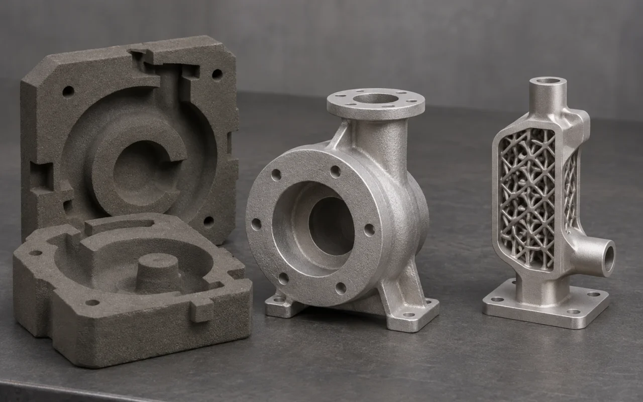
For medium-to-large housings and pump bodies made from established casting alloys, companies with existing foundry capabilities should prioritize 3D-printed sand molds followed by casting. Printing produces the complex molds and cores, while pouring forms the metal body. This retains established casting capacity while reducing the design constraints imposed by patterns and core boxes. Direct metal printing offers greater value when performance depends on fine lattices, compact heat-transfer structures or part consolidation.
This article uses laser powder bed fusion (LPBF) as the representative direct metal printing process. The main differences lie in how the metal takes shape and which structures each route can produce economically.
Cost differences start with how the metal is formed
The sand route prints molds and cores before mold assembly, melting, pouring and post-casting operations. The printer creates the tooling needed to form the cavity; liquid alloy fills it to produce the metal body. For parts already suited to casting, this route uses existing melting, pouring and machining capabilities, concentrating the new digital manufacturing capacity on mold and core production.
LPBF uses a laser to melt metal powder layer by layer. Material expenditure, machine occupancy and post-processing relate to solid metal volume, build height, supports and nesting. Under comparable processing conditions, a larger solid volume means more powder incorporated into the part and more laser processing. Reproducing a relatively bulky conventional casting in LPBF without changing its structural function does not automatically create an economic advantage. EOS’s cost explanation includes powder, machine operation, support removal, heat treatment and finish machining.
Sand printing also incurs costs associated with the build envelope, sand-part volume, print height, cleaning and assembly. Its economic rationale is to print the complex cavity tooling and form the metal body by pouring. When an established casting process is available and the target is a medium-to-large conventional casting, prioritize this combined route.
Split sand molds can still produce a one-piece large casting
A major advantage of printed sand casting is that segmentation can take place at the mold and core stage. Individually printed sand parts are located and assembled before the metal is poured as one casting. Segmentation adds sand-part assembly work without necessarily adding welds to the final metal component.
If an LPBF part exceeds the machine’s build volume, the alternatives include a larger system or printing separate metal sections and joining them. The latter introduces metal joints, joining operations, distortion control and inspection. Both routes can use segments, but their consequences for the final product differ.
For medium-to-large housings and pump bodies that must be delivered as one-piece castings, prioritize split sand molds assembled before pouring. Mold walls and gating and feeding features also occupy space, so print planning should use the actual mold and core dimensions. See the sand printing workflow from CAD to cleaning for the complete sequence.
Curved passages and fine lattices favor different capabilities
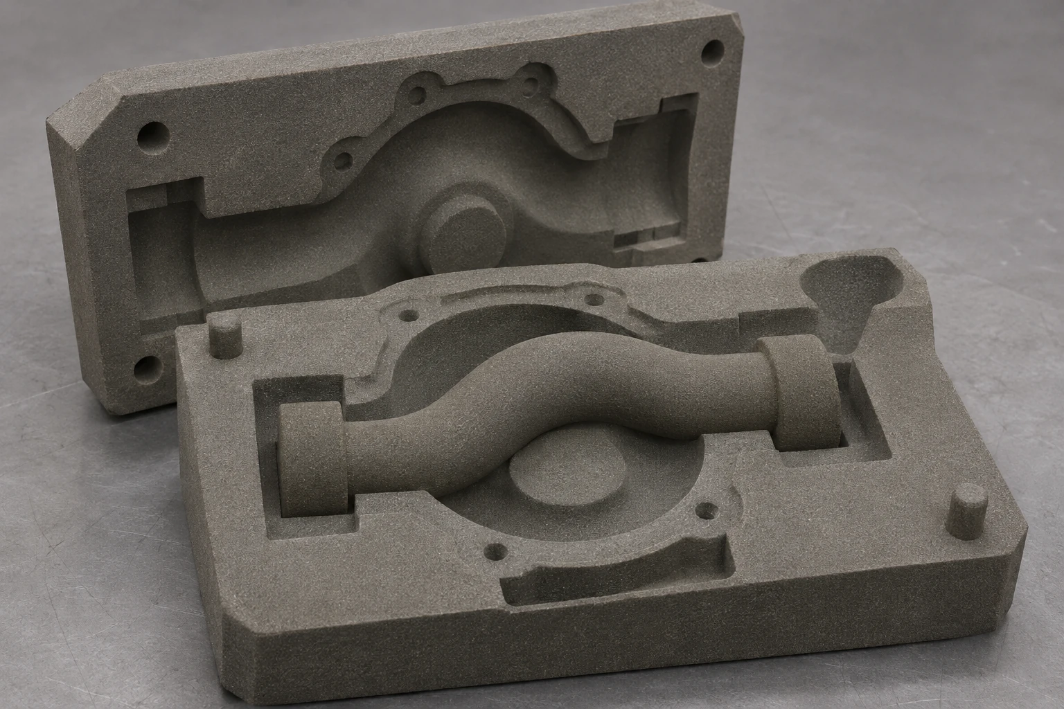
Housings with complex water jackets and curved passages are typical opportunities for sand printing. Directly printing the core enables geometries that are difficult to extract from conventional core boxes. Some designs that previously required several assembled cores can also become more complete single cores, reducing assembly interfaces. Passage complexity alone is not a reason to adopt metal printing.
The downstream casting process still defines the limits. Very fine cores can be damaged during cleaning, handling or pouring, while filling and solidification constrain small metal sections. A printed core must do more than reproduce a shape: it must perform its role in forming the casting.
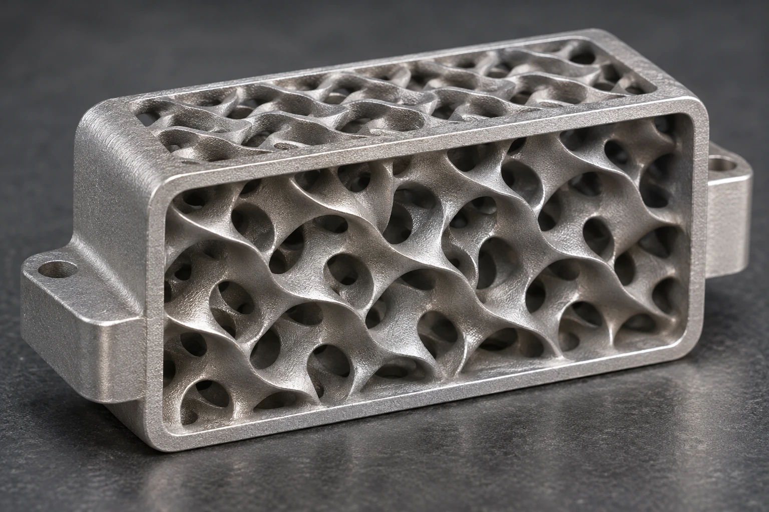
Fine lattices, dense heat-transfer surfaces and compact integrated functional structures make better use of LPBF’s layerwise metal formation. No solid sand core has to occupy every internal space; the process builds the fine features directly in metal. EOS’s public Conflux heat-exchanger example uses additive design to increase heat-transfer surface area within a limited volume, illustrating this functional value. EOS heat-exchanger applications
Prioritize the sand route for castings defined by curved water jackets and complex cores, and LPBF for designs defined by fine lattices and compact heat-transfer structures. Part consolidation adds value when it actually reduces assembly, joints or potential leakage interfaces. Merely changing how an existing casting’s exterior is manufactured does not capture those benefits.
Turn internal-cavity limits into concrete design actions
The sand route needs ways to locate the core and remove it. For an excessively slender core, adjust its support, split it or revise its assembly arrangement. A passage without a sand-removal outlet needs a process opening or a changed layout. Printing reduces conventional draw-direction constraints; filling, feeding and sand removal remain design responsibilities.
LPBF internal features require attention to build orientation, thermal distortion and support accessibility. Supports carry overhangs, conduct heat and stabilize the build. Where internal supports cannot be removed, change the orientation, use an appropriate self-supporting cross-section or revise the segmentation. Design and process optimization can reduce supports, so an overhang alone does not make every feature unmanufacturable.
A fully enclosed cavity that must contain no residual core or powder needs a cleaning access and closure strategy before manufacture. Incorporating those openings and closure locations into the product design makes it possible to clean and deliver the complex internal geometry.
Choose by typical part and manufacturing goal
| Part or manufacturing goal | Preferred route | Main reason |
|---|---|---|
| Medium-to-large housings and pump bodies in established casting alloys | Printed sand molds followed by casting | Forms the metal body by pouring and uses existing foundry capabilities |
| Castings with curved water jackets and complex passages | Printed sand molds followed by casting | Prints complex cores directly, reducing core-box draw and core assembly constraints |
| Parts whose function depends on fine lattices or dense internal heat-transfer structures | LPBF | Builds fine metal structures directly for weight reduction or heat transfer |
| Functional parts that use fine internal structures to consolidate several components | LPBF | Creates internal functional geometry while reducing assembly and joining interfaces |
Select the material together with the application. The sand route uses the relevant casting alloy and heat-treatment system; LPBF uses the corresponding powder and build process. Similar material names do not remove the need to define final properties and acceptance criteria. Align both quotations to the same function and delivered condition.
Compare delivered-part costs and specify the mold-making task
A sand-route quotation should cover mold and core production, mold assembly and pouring, shakeout and fettling, heat treatment, machining and inspection. An LPBF quotation should include printing, depowdering, support removal, heat treatment, finish machining and inspection. Only a consistent delivery scope allows the actual cost per accepted metal part to be compared. Drawings and production quotations determine the price difference; a sand-mold price or metal printing machine-hour rate alone omits part of the work.
Printed sand casting combines complex cavity tooling with established metal casting. LPBF puts fine structures, lightweight design and integrated functions directly into the metal part. Investment in each route should correspond to the manufacturing problem it solves.
For foundries adding complex mold and core manufacturing capacity, the Cprint 3D SJ-1200 sand printing system serves the mold- and core-making stage. Bring representative casting and core drawings, target alloys and capacity requirements to the Cprint 3D team to discuss machine configuration and integration with your casting workflow.