

Two batches of pump housings made to the same revision end up together after shot blasting. They look identical. Each carries P27-A, so you know the part and revision. Which batch did each housing come from?
Cast a batch code beside the part number. Use B01 for the first batch and B02 for the second, and link each code to its pouring record. Then you can sort the housings by reading each mark after cleaning. Here’s where to put the code, how to mirror it in the mold and when to check it on the casting.
1. Choose the code that identifies each batch
Before releasing the print file, decide how precisely the shop needs to trace the housings.
- Part and revision: Both batches carry P27-A. Keep it in the master model.
- Batch: Add B01 or B02. Record the print file, mold lot and pouring record that each code identifies.
- Individual casting: Assign a unique serial number if you need to trace one specific casting.
If the actual heat is assigned after the mold is printed, check the customer’s traceability requirements. The batch code can be linked to the eventual heat record, or an approved mark can be added after casting. If the actual heat number must be cast in, it has to be assigned before printing.
2. Put it where it will remain visible after machining
Work backward from the delivery condition. A pump flange’s sealing face is often machined, so lettering there may be cut away. Evaluate an as-cast area on the outside of the housing instead. Confirm wall thickness, access for cleaning and the viewing direction. If the mark has to be read in service, check the assembled view as well. Keep lettering clear of parting seams, gate or riser removal zones, clamping and mating faces, and areas designated as critical to the part’s strength.
On the casting drawing, define the marking zone, content, reading direction, relief, dimensions and inspection condition. Specify an envelope limit if the lettering has to fit within one. The SFSA guide to drafting practices for castings calls for the location, size and shape of cast lettering to appear on the engineering drawing.
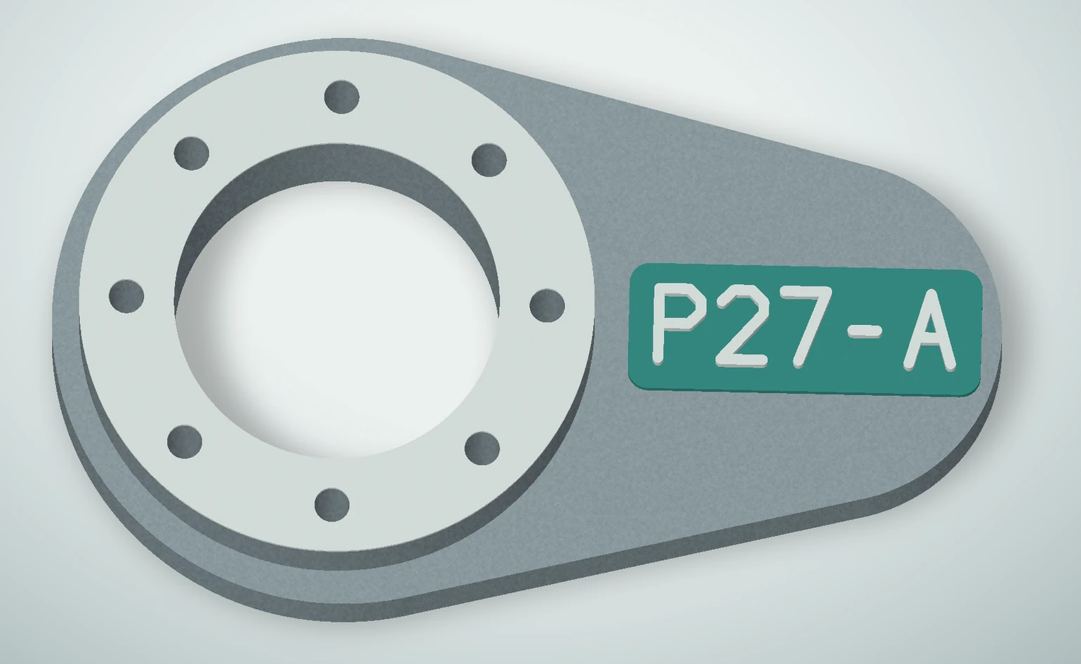
3. Mirror the mark in the cavity so it reads correctly on the casting
Model the part number and batch code as readable text on the casting blank. Subtract that solid from the mold solid in CAD to generate complementary features. If you draw directly on the cavity face, mirror the whole string and check the relief in section. Reversing the order alone leaves each character facing the wrong way.

| Requirement on the casting | Geometry on the cavity face | What to check |
|---|---|---|
| Raised lettering | Mirrored grooves that fill with metal | Can the grooves be cleared of loose sand and filled at the narrowest stroke? Will the raised features clear the assembly and survive grinding? |
| Recessed lettering | Mirrored sand ribs that project into the cavity | Can the ribs survive handling and mold preparation? Does the recessed mark leave sufficient wall thickness and stay readable under the coating? |
| Raised lettering within the part envelope | Complementary geometry for raised lettering on a locally recessed pad | Check the remaining wall under the pad and the height of the letters against the allowable envelope. |
4. Check the character size on a trial coupon
Use the actual batch code on a coupon. Letters and digits such as B and 0 have enclosed spaces where loose sand can collect. Change one variable at a time, whether character height, minimum stroke width, spacing or relief. That makes a missing or merged stroke easier to diagnose.
Use the intended production sand, binder, build orientation, mold coating if applicable, alloy and finishing sequence. Check the mold for loose sand in narrow grooves or damaged ribs, then see whether metal fills the fine strokes on the first casting. Record the dimensions that stay readable and the trial conditions on the drawing or process sheet.
5. Read the mark and look up the batch at first-article inspection
| Checkpoint | Acceptance check |
|---|---|
| Drawing and print file | The string, revision, location, reading direction and relief agree. Any variable identifier maps back to the correct file. |
| Mold after depowdering and specified treatment | The mirrored lettering is correct. Grooves are clear, ribs are intact and coating has preserved the detail. |
| Casting after cleaning and agreed finishing | Compare characters one by one with the record or drawing. Look for missing or merged strokes, obscured marks and clearance or height issues. |

At first-article inspection, read the batch code and use it to retrieve the matching mold and pouring records before releasing the batch. Save a photo with those records. If castings from both batches end up in the same bin, the code on each one gives you a way to sort them back.
For the full sequence from molding to cleaning, see our sand casting process guide. For the traditional method using embossed foil on a pattern, see Industrial Machinery Digest’s report on pattern labeling.