
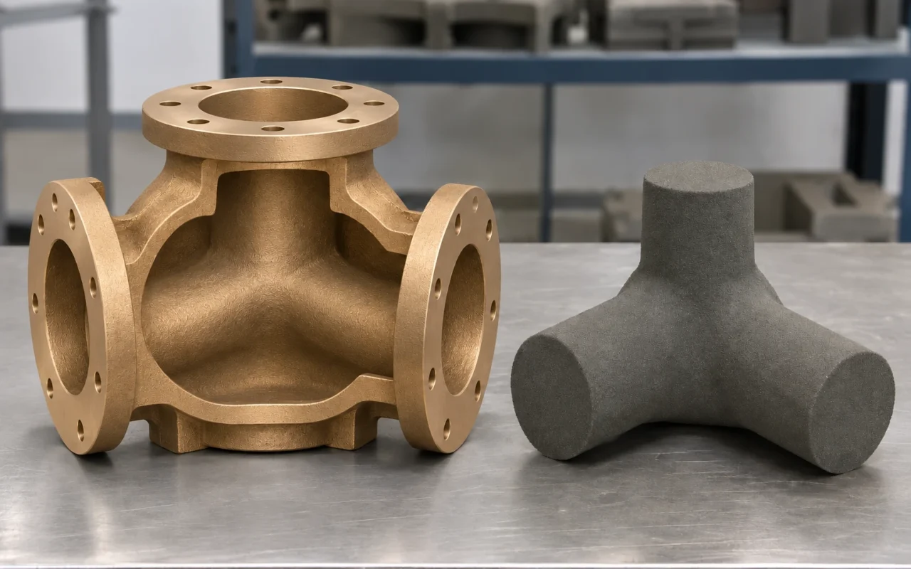
Imagine a bronze valve body with flanges at its ends, a central chamber and a passage that turns inside the metal housing. How is that hidden space left open during pouring?
A sand core occupies the space that will become the passage. Molten bronze solidifies between the core and the outer sand mold; removing the core after casting reveals the channel. 3D printing can produce these molds and cores directly, providing another way to form complex cavities while reducing dependence on dedicated patterns and core boxes.
For bronze pump bodies, valve bodies and branching fittings, the engineering task is to turn passage geometry into a mold-and-core design that can be supported, located, assembled and cleaned.
Print the molds and cores, then pour the bronze
In binder jetting, for example, the printer spreads sand in layers and selectively applies binder according to the digital model. The resulting molds and cores are cleaned and assembled before pouring. The metal component is then produced by melting, pouring and solidifying the bronze. This separates the route from direct 3D printing of bronze parts. For the basic objects and stages, see the sand casting process.
Published applications include bronze pump components. ExOne describes a project in which Speed 3D Mold produced molds and cores for lead-tin-bronze double-suction impellers, illustrating a specific use of printed sand components in complex pump casting. ExOne project report
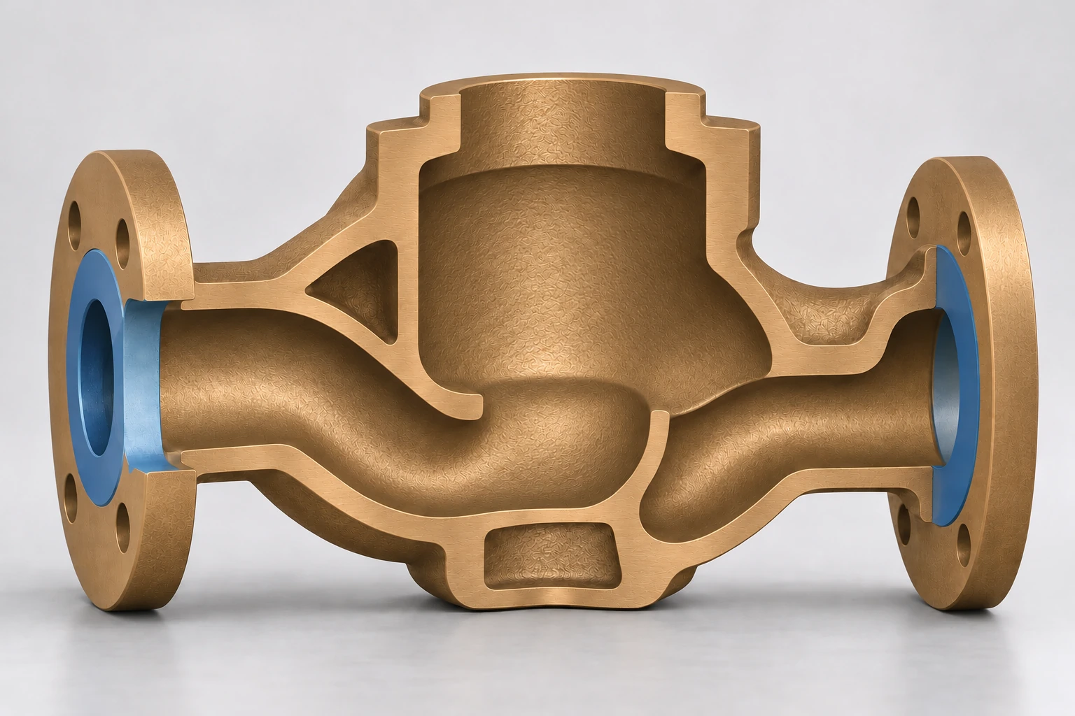
Start with the bronze grade and casting requirements
C90300 is a tin bronze whose manufacturer-listed applications include pump bodies, impellers and valve bodies. C95800 is a nickel-aluminum bronze with listed uses including valve bodies, valves in contact with seawater and elbows. For an individual part, the service medium, operating conditions and drawing should establish the alloy grade, material specification and required delivery condition. C90300 material information; C95800 material information.
The drawing should also identify as-cast surfaces and machining areas. Flange faces, sealing faces, mating bores and threads affect machining stock, datum selection and workholding. Define whether the delivery is a casting blank or a component that has completed machining and the specified tests.
Converting the finished-part model into casting data involves three separate tasks. Dimensional shrinkage compensation accounts for dimensional changes as the casting cools. Machining allowance reserves metal for subsequent cutting. Solidification feeding supplies liquid metal to the regions that require it. The designer and foundry should establish these provisions together, along with sand, binder and mold/core treatment suited to the selected bronze.
Four priorities in core design
Support and location. Core prints and the corresponding seats in the outer mold support and locate the core. Long cantilevers, narrow necks and asymmetric branches need assessment for handling loads, movement or flotation during pouring, molten-metal forces and thermal deformation. Base the locating scheme on critical wall thicknesses, passage position and machining datums, checking how core shift would affect local walls and interfaces.
One-piece or segmented construction. Printing a core in one piece can reduce assembly interfaces; segmentation can improve access for depowdering, coating, inspection and handling. Design the parting surfaces, mating features and assembly sequence together, considering passage steps, flash and local wall thickness. Original research discusses mold partitioning to improve cleaning access and provides a basis for reviewing difficult regions. Research on cleaning and partitioning.
Depowdering before pouring and decoring after casting. The first removes loose sand from sand-part surfaces, mold cavities and spaces between branches; hollow cores or internal vent spaces also require access where included in the design. The second removes core sand from the solidified metal cavity. Review bends, blind ends, section changes and branch junctions for cleaning openings, tool paths and inspection methods at both stages.
Venting. Sand permeability, designed vent passages and metal-filling channels serve different functions. The foundry should define gas escape paths and outlets for the mold/core arrangement, checking their relationship to the finished component’s pressure boundary.
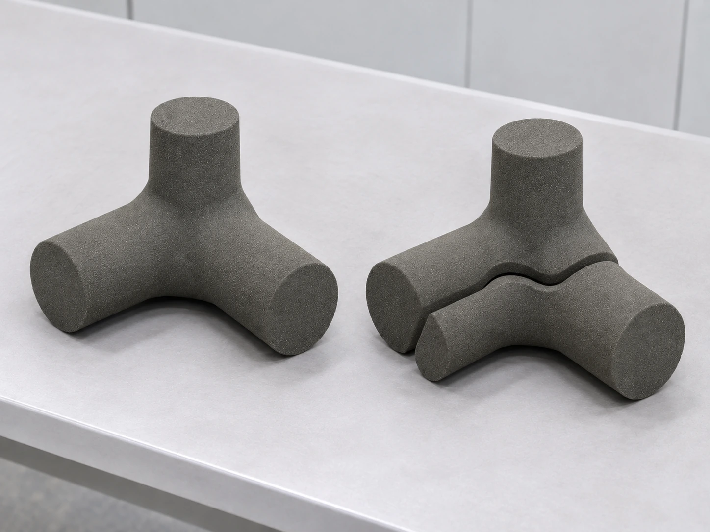
From print preparation to post-casting machining
Once the model and drawing revisions are established, complete the casting-blank and process design. Incorporate compensation, machining stock, mold/core segmentation, core prints and seats, gating, risers and vents into the digital data. Review important filling and solidification issues using simulation and foundry experience as appropriate, then verify the approach through trial casting.
Print preparation should address sand-part orientation, fragile features, unpacking space and nesting efficiency. After printing, unpack, clean and carry out the treatments required by the material system; inspect surfaces, dimensions, joints and locating features. Apply coating and drying according to the process plan. Research on furan-bonded sand shows that binder, sand-grain conditions and curing influence mechanical and technological properties within the systems tested. Research on furan molding and core sands.
Before core setting and mold closure, use trial assembly to check joints, location, assembly order and interference. Mold-closing checks should cover gating, feeding and vent paths, with loose sand and foreign material removed from the cavity.
The foundry then establishes melt treatment, pouring temperature, filling, feeding and cooling for the bronze grade, wall-section changes and mold/core conditions. Transitions around flanges, corners and valve chambers deserve attention in this review.
After casting, arrange shakeout, decoring, removal of gating and risers, and cleaning, followed by heat treatment, machining and inspection as required by the material specification and delivery scope. Establish how curved passages will be decored and inspected during the mold/core design stage.
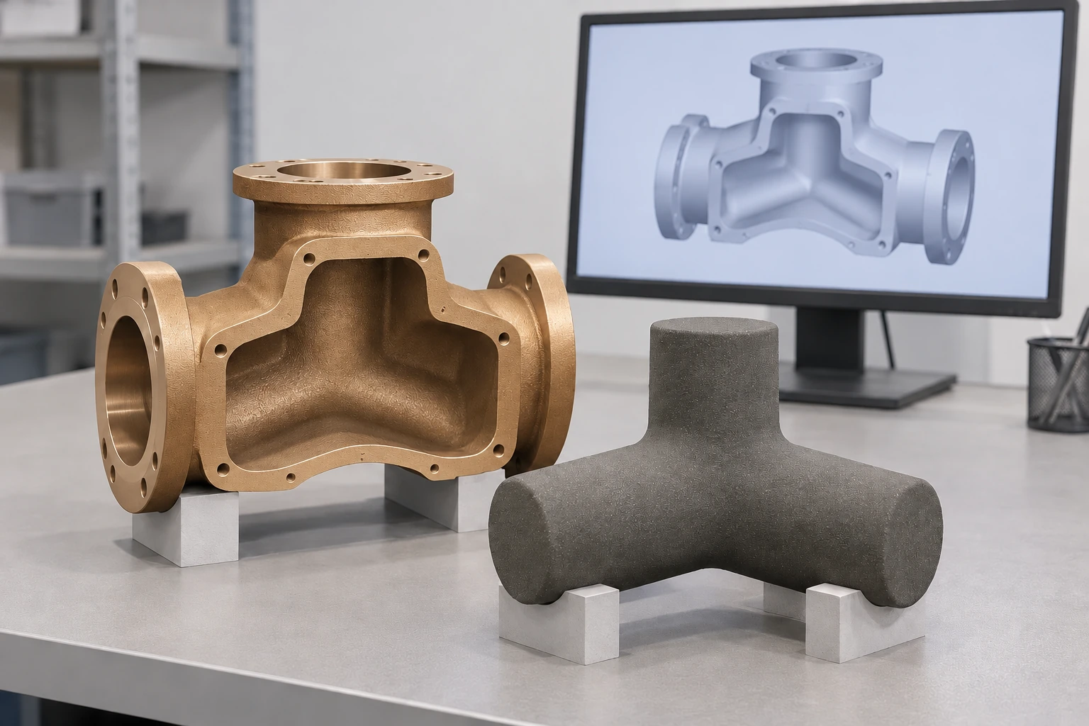
Inspect passages, walls and functional requirements
Keep dimensional records for four stages: sand components, assembled molds and cores, as-cast parts, and machined parts. This helps trace deviations. Sand-printing dimensional specifications apply to checking the sand components; finished-part tolerances are accepted against the component drawing.
Passage inspection should address position, critical sections, local wall thickness and residual sand. Select methods for the geometry and available access, including direct viewing, borescope inspection or suitable nondestructive testing. Investigate abnormalities against relevant process factors, such as core shift, sand-part damage or erosion, gas, filling and feeding.
Include material documentation, dimensional checks and functional tests in the acceptance scope. For pressure-containing and sealing components, the applicable specification, drawing or contract should define the stage, conditions and acceptance criteria for pressure or leak testing.
Print a complete mold set or only the complex core?
Printed sand components deserve early consideration when complex cavities require many conventional core-box sections or difficult assembly, or when new parts and revisions frequently change the tooling. Prototypes, replacement parts without the original pattern and complex low-volume castings can also be assessed against the work of preparing dedicated tooling.
Where established outer tooling remains suitable, conventional molds with printed sand cores concentrate printing on the difficult internal geometry. Consider a complete printed mold-and-core set when both the external and internal geometry need new preparation. Retaining the conventional route also has practical value for simple parts with mature tooling and stable repeat production.
Compare cost and lead time for the same alloy, quantity and acceptance scope, including data preparation, sand-part production, cleaning, assembly, transport, casting, machining and inspection. Sand-part size, segmentation, handling strength and passage-cleaning difficulty all affect the complete delivery.