
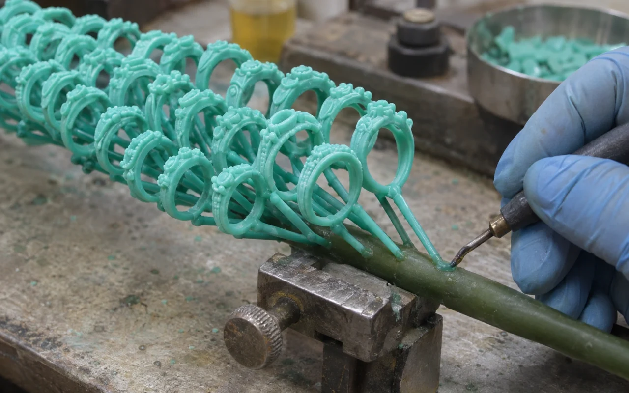
A wax tree connects multiple patterns to a gating system. It is both the assembly around which the casting mold is made and the arrangement of passages through which metal reaches the parts. An intact printed model does not guarantee a sound casting when attached anywhere on the tree. Connection positions, pattern spacing, assembly orientation and subsequent gate removal all belong in the casting plan.
Understanding the wax tree helps printing teams avoid treating print supports as ready-made sprues or filling a tree so densely that investing and shell building become difficult. Tree assembly should serve the complete manufacturing process, rather than maximize the number of patterns on one tree.
Separate the Roles of Patterns and Sprues
The wax model mainly expresses the shape of the part. The runner system connects the gate, main trunk, branch and model, and is responsible for the path of metal entering the cavity. The Investment Casting Institute’s group instructions link the wax pattern assembly to the subsequent metal flow path, so the wax pattern should be reviewed as part of the casting design. Wax tree assembly instructions
The purpose of printing supports is to help the model maintain the predetermined geometry during the forming process. Its position and shape serve the printing task first and do not naturally meet metal flow, feeding or removal requirements. Even if a section of structure looks like a connecting rod, it needs confirmation from the casting staff before it can be given sprue functionality.
Frames used for handling or positioning should also be specified. The existence of a rod in the design file does not indicate whether it will ultimately belong to a part, a sprue, or a temporary auxiliary structure. Labeling these three types of structures separately allows de-bracing, tree assembly and inspection personnel to follow the same instructions.
Plan Connections Around Casting and Finishing
Where the sprue is connected should be determined based on the thickness of the part, the local structure and the casting plan. Parts of different alloys and different shapes cannot be covered by phrases like “attached at the thickest point” or “attached at the back.” The designer needs to give the finished product requirements, and the casting personnel will judge the connection plan accordingly.
The appearance surface, subsequent inlaid area, mating surface and the inner side that is not easy to be repaired should be marked in advance. Although it is easy to connect somewhere, it may leave traces that are difficult to deal with after removal; although a hidden part does not affect the front appearance, it may be inaccessible for tools.
Formlabs’ Jewelry Casting Guide also discusses mold-to-sprue connection arrangements. Its materials and operating conditions are specific to the resin system and cannot be directly applied to the wax spray process, but it prompts a common communication problem: the printing structure and the casting connection need to be designed separately. Jewelry Model Casting Guide
For example, for rings with thin claws, the connection parts, claw protection and sprue removal sequence should be confirmed separately. If the connection is close to the key insert, whether subsequent processing will affect the shape needs to be discussed before assembling the tree. There is no sprue diameter or fixed angle that applies to all rings and should be confirmed by the casting party on an actual project basis.
Allow Mold Material to Reach Between Patterns
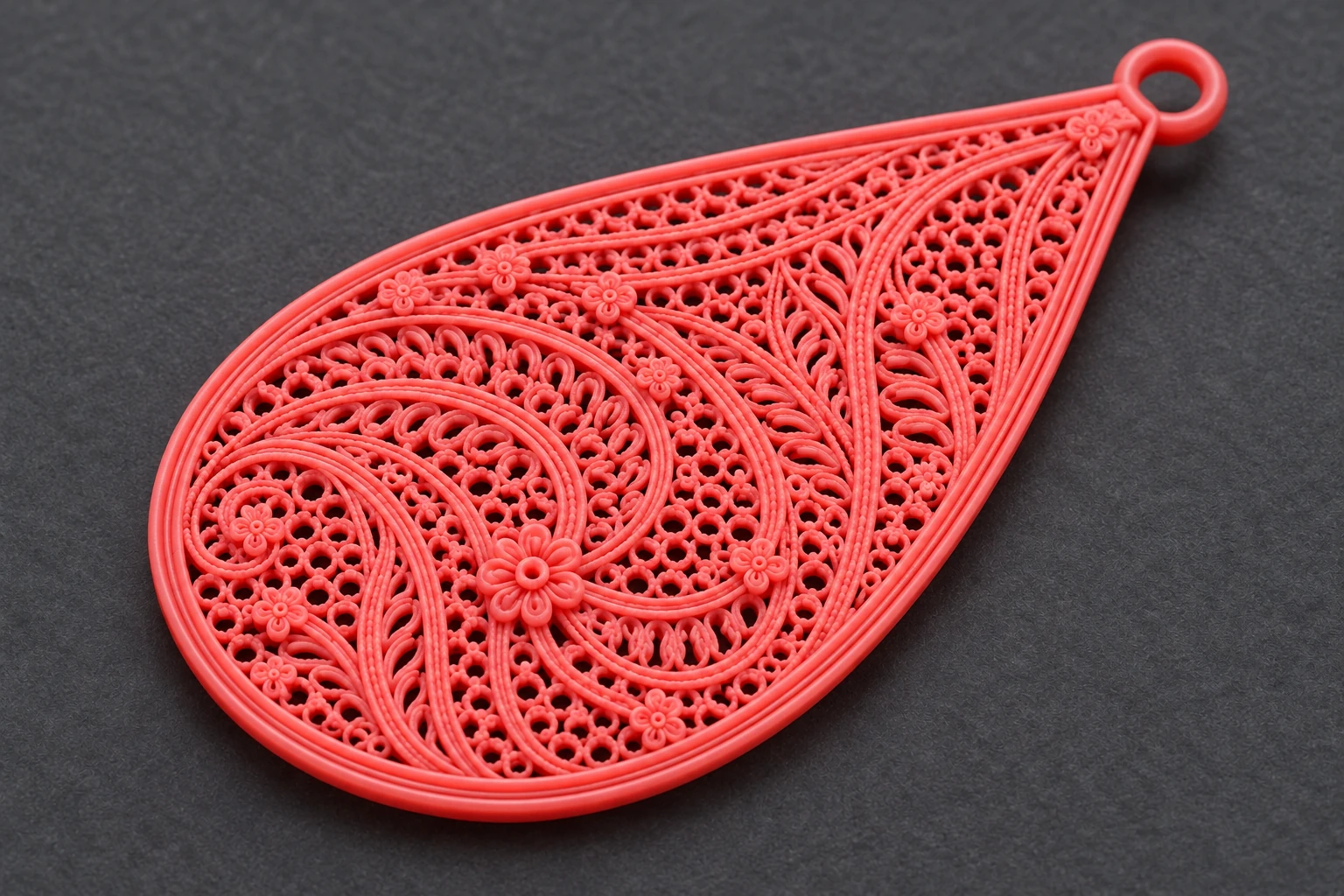
The close proximity of the two wax pattern models may increase the number of assemblies, but reduce the space for embedding slurry or shell making operations. The gaps between hollow patterns, curved thin rods and deep grooves on the back especially need to be observed from the actual process direction.
When embedding, consider slurry entry and bubble inspection; when making shells, consider slurry dipping, drainage, sand spreading and drying. A layout that appears to work for one method may not necessarily work unadapted for the other method. When confirming spacing, the person making the cast should be able to see the complete wax tree, not just the individual model.
Also consider the rigidity and handling location after assembly. If the entire tree can only hold onto a weak model, the operation may introduce additional damage. Reserve a suitable holding and fixing area for the tree, which is more reliable than asking the operator to temporarily find a landing position.
Inspection space is also worth preserving. If the inner details cannot be seen after the connection is completed, it will be difficult to determine whether there is damage, residue or misassembly. The design plan should include observation angles, photograph key parts before connection if necessary, and keep corresponding records before and after assembly.
One Print Batch Does Not Have to Become One Wax Tree
Printing and typesetting can arrange multiple models in one job, but the casting group tree also needs to consider the alloy, casting system, size, delivery batch and process conditions. Models that can be printed together do not mean they are suitable for casting together.
For example, two pendants with similar appearance may have different target alloys and surface requirements. When printing, they can be identified and sorted uniformly, but when grouping trees, they need to be separated according to casting tasks. If only classified according to the pallet position, the corresponding relationship between order and version will be easily lost after the model leaves the printing platform.
Even if the alloy is the same, the casting party should be asked to confirm whether the structural differences allow for mixed trees. Models with obvious changes in thickness, fragile models and proven stable styles may have different trial production purposes. In order to facilitate the interpretation of results, first-round validation sometimes requires maintaining clearer sample groupings.
The group tree record should at least contain the tree number, model number, version, quantity and location indication. In this way, when a problem occurs repeatedly at a certain location, it can be traced to its location on the tree and adjacent structures, rather than lumping the entire problem together as “this batch of wax doesn’t work.”
It is recommended to set “printing platform position” and “wax tree position” as two independent fields, and use the same model number to connect the two position maps. After the model is sorted or reorganized into trees, the new tree number and location are retained to avoid being left with only photos of the original pallet and unable to trace subsequent castings.
Make Tree-Assembly Release Traceable
| Release issues | results to be left |
|---|---|
| Which confirmed version does the model come from? | File version corresponds to model number |
| Who approves connection locations and sprue plans | Confirmor, date and plan version |
| Which surfaces need protection? | Marking of appearance surface, mating surface and inlaid area |
| Can the mold material reach key details? | Whole tree and local observation records |
| How to transport and secure wax trees | Holding position and delivery status |
| How to track down casting problems | Tree number, location, alloy and casting batch |
When releasing, check whether the physical object is consistent with the approved plan. Temporarily adding models, changing positions, or changing connection methods on site may affect subsequent judgments. If changes are indeed needed, the changes should be recorded and reconfirmed by relevant personnel.
If the model on the tree has cracks or defects, it should not be released directly on the grounds that “there will be metal processing later”. Whether it can be repaired and whether it will affect the size and appearance must be evaluated according to project requirements. In particular, records of treatment and re-examination need to be kept for injuries to critical parts.
For repeat orders, the approved group tree can be saved, but the current model version and casting conditions still need to be checked. New bead size, local thickness or surface requirements may cause the old plan to need to be reviewed. The premise of the reuse scheme is that the applicable conditions still hold, and the same cannot be determined based on the style name alone.
Link Casting Feedback to the Corresponding Tree Position
When a casting has insufficient mold filling, surface anomalies or dimensional problems, first find the corresponding model, tree number and location, and then check the geometry version, wax pattern status and casting records. Location relationships can provide clues for troubleshooting, but they cannot alone prove the cause.
You can use the whole tree diagram to mark abnormal parts, and then compare the results of adjacent parts and other positions of the same style. If there is an abnormality in only one position of the same model, a hypothesis should be made based on the connection, space and process records of that position; if similar problems occur in multiple positions, the scope of inspection needs to be expanded.
When verifying improvements, it should be clearly stated whether the connection position, model spacing, or other process conditions have been changed in this round. Changing multiple factors at the same time may lead to better results, but it is difficult to determine which factor is responsible. Only by retaining a record of changes can the group tree have a basis for reuse next time.
Keep a Comparison When Connections Change
When trying out different connection positions for the same style, you can keep two approved plans and make the model number correspond to the plan. When giving feedback, check the casting performance near the connection and the state after removal. This allows you to discuss the casting results and compare finishing work on the finished product, avoiding making decisions based solely on a photo of the sprue not removed.
Frequently Asked Questions
Is a More Densely Loaded Tree Always More Economical?
It needs to be judged based on the number of qualified castings, the total workload of mold making, pouring and subsequent processing. Overpacking that is difficult to cover, inspect or clean may increase the risk to the entire batch.
Can Sprues Be Printed with the Patterns?
It can be given to printing and casting personnel for evaluation as a solution option, but the geometry, materials, connection strength, assembly and subsequent processes must be confirmed separately. Being able to generate the entire tree in the software does not mean that the tree has been released for casting.