
From digital geometry to casting wax patterns
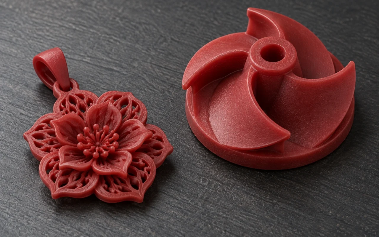
A red wax ring model already shows its setting, shank and surface texture, but it still needs casting to become a metal jewel. The same applies to an impeller or another industrial wax model: printing creates a physical pattern from digital geometry, and casting makes the transition to metal.
Wax 3D printing builds casting patterns layer by layer from prepared digital models. Follow three objects to understand the process: the digital model defines geometry, the physical wax pattern helps form the mold, and the resulting mold cavity receives metal. Printing changes how the wax pattern is made, while design, support removal and casting must work together to produce a usable part.
1 What the wax pattern does in casting
A wax pattern is a positive form whose physical surfaces define the shape to be reproduced. In lost-wax casting, patterns are combined with a gating system and surrounded by a refractory mold. Removing the wax leaves cavities for metal. Jewelry commonly uses investment molds, while industrial investment casting often uses ceramic shells; the project process determines the system.
With a ceramic shell, for example, successive layers are built around the wax tree. Once the shell reaches the required condition, dewaxing is followed by shell firing, pouring and post-casting operations. Pattern production sits near the beginning of this chain, and its geometry and surface condition carry through to later stages. the Investment Casting Institute’s process overview shows the sequence.
Printed objects are often called wax models in general conversation. Distinguish the casting pattern from the wax injection die used to reproduce patterns and the refractory mold that holds molten metal. Wax model is natural for general introductions; wax pattern is the specialist term in investment casting.
Direct pattern printing can reduce dependence on dedicated wax tooling, but casting still requires a mold. CAD may also include machining allowances or process compensation, so a production pattern need not have exactly the finished part’s dimensions. These differences should have a clear design basis.
2 How digital geometry becomes a wax pattern layer by layer
First, CAD geometry must become data the printing system accepts. Build preparation software considers orientation, supports and layout to produce an executable job. Slicing divides the model into cross-sections along the build height, identifying where material is needed in each layer.
In hot-melt wax jetting, wax in a suitable jettable state is deposited by a printhead at the required locations. It cools and solidifies into a layer before the next layer is built. Successive cross-sections create the height, curves and local details of a three-dimensional pattern. Piezoelectric printheads depositing casting wax layer by layer are one implementation of this technology. 3D Systems’ jetting process explanation
Hot-melt wax jetting forms patterns through cooling and solidification, whereas light-cured resin uses different materials and forming mechanisms. Both routes can produce casting patterns, but their post-processing and casting entry conditions must be confirmed separately.
Cprint 3D’s 3H-420 Plus uses multi-nozzle wax jetting to produce wax patterns for casting directly. Evaluate equipment using actual files, materials and job records, checking whether finished patterns meet handoff requirements rather than treating a single specification as a measure of fine detail.
Layer thickness describes spacing between layers; dimensional accuracy describes how measured dimensions relate to requirements. They answer different questions. A smaller layer thickness alone does not establish that a setting, hole diameter or final casting meets a specified tolerance.
3 Why build wax and support wax work together
Complex geometry may have overhangs, thin connections and gaps that need temporary support during printing. In a matched build-and-support system, build material forms the desired geometry while support material helps maintain its shape during construction.
In the 3H-420 Plus material system, red build wax forms the pattern to retain, while white wax-based support provides temporary support. Removing support exposes previously enclosed details for full observation; acceptance inspection should therefore follow cleaning.
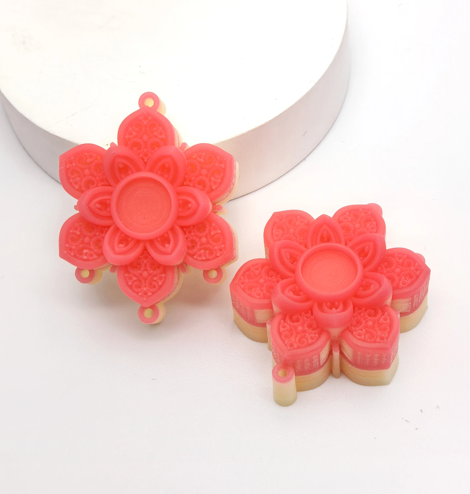
At the end of printing, build and support materials may still form a combined structure. Appropriate support removal produces a pattern suitable for handoff, retaining the build wax. Dewaxing occurs later, after the mold has formed, and removes the build wax itself. The two operations have different targets and purposes.
Support removal must follow the equipment, materials and approved operating procedure. Wax-based material does not automatically mean water-washable, nor does it justify adopting another brand’s temperatures or media. Protect the build wax during cleaning, handling and packing.
Materials for different machines should not be interchanged merely because their colors or melting points are similar. They must meet requirements for jetting, forming, support removal and subsequent casting, with the compatibility verified accordingly.
4 From files to patterns ready for handoff
A complete job can be organized around the following six stages. Clear outputs at each stage make it easier to decide whether the next one can begin.
| Stage | Main work | Expected output |
|---|---|---|
| File confirmation | Check revision, units, quantity and critical geometry | Input files matching approved requirements |
| Build preparation | Review orientation, supports, layout and manufacturing adjustments | An executable, traceable job |
| Printing | Run the job under the required equipment and material conditions | A build-and-support structure awaiting removal and post-processing |
| Support removal | Remove the build and its supports using the appropriate method | A wax pattern ready for complete inspection |
| Inspection | Check critical dimensions, details, residue and damage | A release decision or specific nonconformity record |
| Handoff | Group, protect and identify patterns, and transfer process information | Accepted patterns ready for the next operation |
Wukong handles slicing, layout and build preparation. Jewelry modeling and engineering design remain part of the relevant CAD workflow. Confirm file formats, software functions and processing steps against the version actually used.
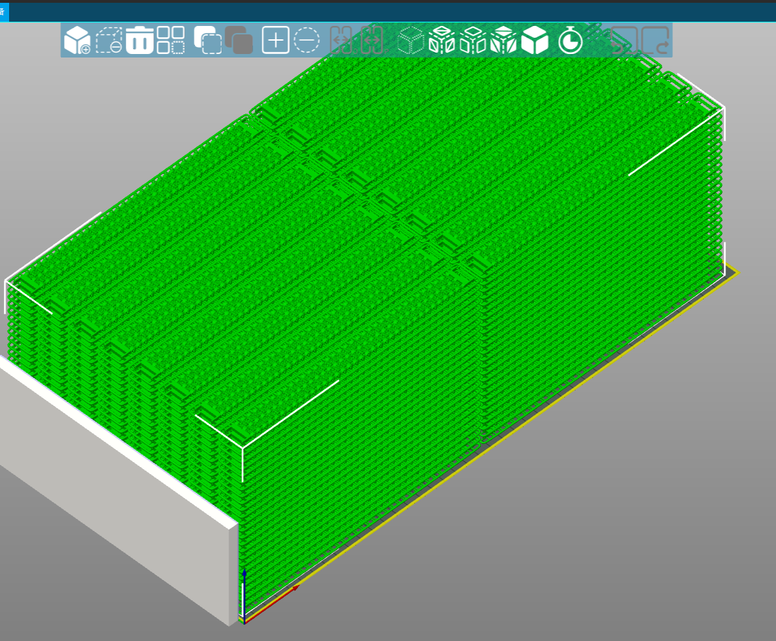
A seemingly complete file can still contain unit, mesh or local geometry problems. Check overall dimensions and critical areas before job preparation. After repairs or compensation, compare against the original design to confirm that no unapproved changes have occurred.
After printing, focus on areas previously hidden by support. Fine prongs, through-holes, recessed textures and thin connections need suitable observation and measurement methods. Measurement must also avoid deforming the wax under load.
Final handoff records include style or part number, revision, quantity, inspection status and key process requirements. When supplying another organization, confirm packing, transport and receiving methods as well. The machine’s finish time is not the time a customer receives accepted patterns.
Information to supply with the patterns
Provide the approved file name and revision, style and quantity, key inspection records and any adjusted areas. Recipients should know whether they have production patterns, validation samples or patterns requiring reinspection, so similar appearance does not become the sole basis for proceeding.
For example, a ring used to validate a setting should identify the measurement basis and any manufacturing adjustments already included. An industrial pattern used to validate geometry should state whether a casting trial is planned and which requirements still need checking in metal. Clear validation objectives make sample results interpretable.
Reconfirm pattern condition for repeat orders
Saved digital files support repeat orders, but materials, job conditions and requirements still need checking for each run. A revision change, different cleaning method or new foundry may require renewed handoff agreement. Unchanged CAD does not remove the need to inspect the current patterns.
For unsettled geometry, first record forming, cleaning and inspection results for a representative feature, then decide whether to proceed to the full part. The complete part still needs handling and downstream manufacturing review; feature validation informs evaluation without releasing the entire part.
For tree assembly, shell building and pouring after pattern handoff, see Wax Pattern Post-Processing and the Lost-Wax Casting Workflow.
5 Jewelry jobs worth evaluating
Custom revisions, multiple sizes, local textures and mixed orders create different pattern-making needs. Digital files make revisions easier to retain and jobs easier to reschedule, while each change still calls for checks of the affected dimensions and manufacturing conditions.
Changing ring size requires rechecking settings and connections; adding openwork requires cleaning and casting review; combining styles in one build requires identification, post-processing and sorting. Assess the technology’s value against the specific order.
For stable repeat designs with accepted tooling and a mature wax injection process, retain that route for comparison. The suitability of direct printing depends on revision frequency, order mix, available resources and cost per accepted pattern, rather than the labels custom or small batch alone.
6 Digital wax patterns in industrial investment casting
Industrial projects can assess printed patterns for design validation, revised prototypes and repeat production. Digital pattern making serves both validation and production, while wax and castable plastic patterns follow their respective material routes. 3D Systems’ investment casting pattern applications
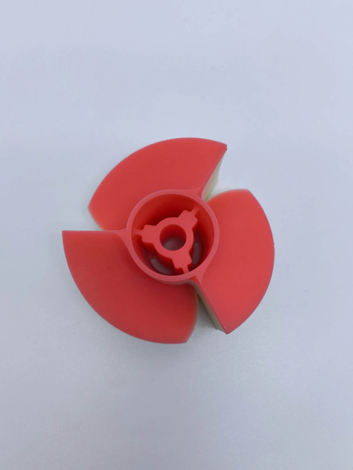
For a specific part, first establish the target alloy, geometry, critical dimensions and machining requirements, then review build space, cleaning, cores and casting conditions. Wax samples help check geometry and process interfaces; material properties and function of the finished part must be validated in metal.
Complex internal geometry needs particular review. A digitally modeled space still needs workable material removal, mold formation and final inspection. Evaluate openings, splitting, cores or alternative manufacturing routes where needed; design freedom does not mean every geometry is ready for direct delivery.
Using wax patterns in both industry and jewelry does not imply identical investing, shell-building and pouring conditions. Before downstream processing, the foundry should confirm compatibility between the wax and the project process and retain trial feedback.
7 Evaluating a wax printing job
Frame evaluation around six questions: are the patterns usable, are critical details intact, can they be cleaned and inspected, does the foundry accept the material, how is total job time composed, and might repeat orders suit another pattern-making route better?
Tie inspection results to specific features. For settings, record the relevant dimensions and condition; for fine mesh, record whether it remains intact after cleaning and handling. Calling a surface attractive does not answer these handoff questions.
Record time separately for file preparation, queuing, printing, support removal, inspection and transport. Vertical build speed describes only part of this process and cannot establish total order lead time. Cost also includes build and support materials, preparation, machine time, labor and rework.
For an initial evaluation, choose geometry representative of order risks and state the expected number of styles, quantity and revision needs. The sample can then validate the current geometry and help plan later batches.
If you are already selecting equipment, use the Jewelry 3D Printer Buying Guide to assess equipment, materials and post-processing conditions further.
Frequently asked questions
Can a wax 3D printer print metal directly?
A wax printer produces wax patterns directly. Gold, silver and other alloy parts require a mold made around the wax pattern, followed by metal pouring and the appropriate post-casting operations.
Can a printed wax pattern be used for repeated castings?
The pattern loses its original shape during wax removal after mold formation, so the same physical pattern cannot be reused for repeated castings. Repeat orders generally require new patterns from saved digital files or a validated tooling-and-replication route.
Is castable resin the same as wax printing?
Both can provide sacrificial casting patterns, but their materials, forming and post-processing differ. A resin with wax in its name cannot simply be treated as build wax; each material needs its own casting validation.
How do I start evaluating my own job?
Prepare CAD files, revision, quantity, critical dimensions, intended alloy and downstream casting conditions, and identify the features to validate. When discussing 3H-420 Plus sample evaluation with Cprint 3D, also share expected style count and revision frequency to assess production needs around accepted wax patterns and casting compatibility.