
Start with what the printer produces
If the goal is a metal piece of jewelry or a component, why print a wax model first? Could direct metal printing eliminate casting? To answer, establish what leaves the printer and which operations remain before delivery.
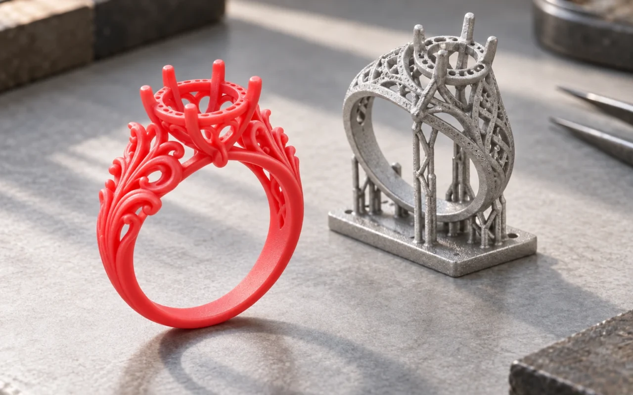
“3D-printed jewelry” and “3D-printed metal parts” can describe different manufacturing processes. One forms metal in the printing system; another prints a wax model and obtains the metal part through investment casting. A similar finished shape does not reveal which route was used.
This article uses laser powder bed fusion (LPBF) as the main example of direct metal printing and compares it with wax jetting followed by casting. The outputs, material inputs and finishing steps differ, so suitability should be assessed against the intended use and acceptance requirements.
1. The printer’s output determines the next manufacturing steps
LPBF spreads metal powder over a build platform. A laser melts selected areas defined by the prepared data to build the part layer by layer. EOS’s overview of DMLS identifies it as an LPBF process and explains the relationship between powder spreading and laser melting.
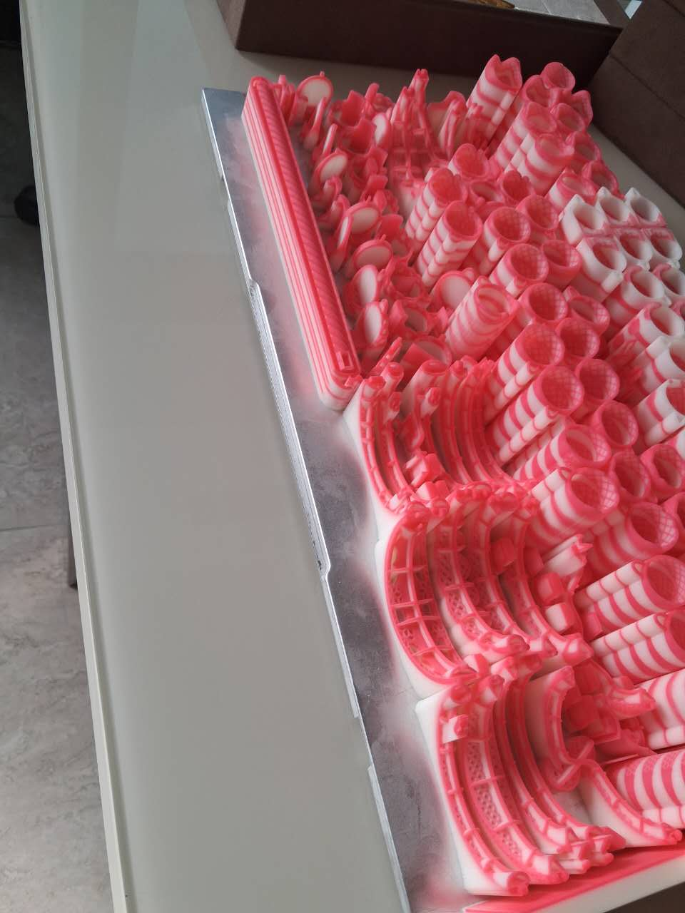
Wax jetting builds casting patterns layer by layer. Cprint 3D’s 3H-420 Plus produces wax models; gold, silver or other alloys take shape during subsequent casting. A printed ring model still needs casting and finishing to become metal jewelry.
The two routes can be outlined as follows:
- Direct metal route: digital design and build preparation, metal printing, the required post-processing, and final inspection.
- Printed wax casting route: digital design and build preparation, wax pattern production and inspection, tree assembly, investing or shell building, dewaxing and burnout, metal pouring, post-casting work, and final inspection.
Here, “direct” means that metal is formed during the additive process. It does not mean that the part leaves the machine with its final surface, dimensions and properties. Other metal additive processes can have different workflows; this LPBF example does not describe all metal printing.
2. Metal enters production at different stages
Direct metal printing requires powder, parameters and processing conditions suited to the equipment. Even when the alloy name is the same, check the feedstock specification, material condition and intended use. A machine’s ability to print metal does not establish compatibility with every alloy.
The wax route uses wax to make a pattern, while the final alloy is selected for casting. The foundry must also establish the suitability of the investment or shell, melting, pouring and downstream operations. A metal-free wax pattern does not make every alloy castable under the same conditions.
The Investment Casting Institute’s process guide presents shell building, dewaxing, metal pouring and post-casting work as linked operations. Assess these capabilities alongside the actual material requirements when considering the wax route.
Jewelry and industrial parts have different objectives. A ring involves wearability, stone setting and appearance; an industrial component may involve assembly, load-bearing or other functions. Material documentation and inspection methods should reflect the application. Similar appearance does not establish equivalent performance.
3. Review the same CAD design separately for each route
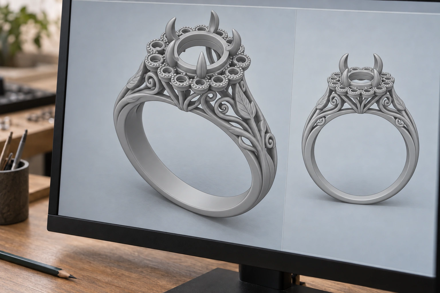
A digital model expresses product requirements, but production preparation may require orientation, supports, compensation or machining allowances. Since preparation differs between routes, sending the same unreviewed file to both suppliers and comparing only their prices is insufficient.
For LPBF, consider powder removal, support access, separation from the build plate and machining of critical surfaces. If a closed space would trap powder that cannot be removed, resolve it during design and process planning.
The wax route needs review of support removal, pattern integrity, tree connections and metal feeding. Also consider how internal spaces will be formed in the mold and whether cores or separate sections are needed. In both routes, creating the geometry and fully processing and inspecting it are different tasks.
Plan finishing access early as well. Tools must reach a ring’s stone setting, while an industrial sealing face needs suitable machining stock and workholding. These decisions affect the result and should be addressed before printing or casting.
Consider a hypothetical ring with an openwork gallery. The direct metal proposal should explain how powder and supports will be removed from the gallery and how support contact areas will be finished. The wax proposal should explain how fine connections will be protected during support removal, whether investment can reach the relevant spaces, and where gates will be placed. Both must explain how the finished setting, gallery and shank will meet the agreed dimensions and appearance.
A structure may be straightforward with one route but require modification or splitting with the other. When a supplier proposes changes, identify the affected areas, the reasons and any impact on function or appearance, then obtain the appropriate approval.
4. The post-processing lists differ
After direct metal printing, operations may include depowdering, part and support removal from the plate, heat treatment, machining and surface treatment. The material, geometry and application determine the necessary combination; there is no single checklist for every part.
EOS’s metal additive manufacturing workflow includes depowdering and post-processing in the chain from data to finished part, with the combination varying by material, geometry and application.
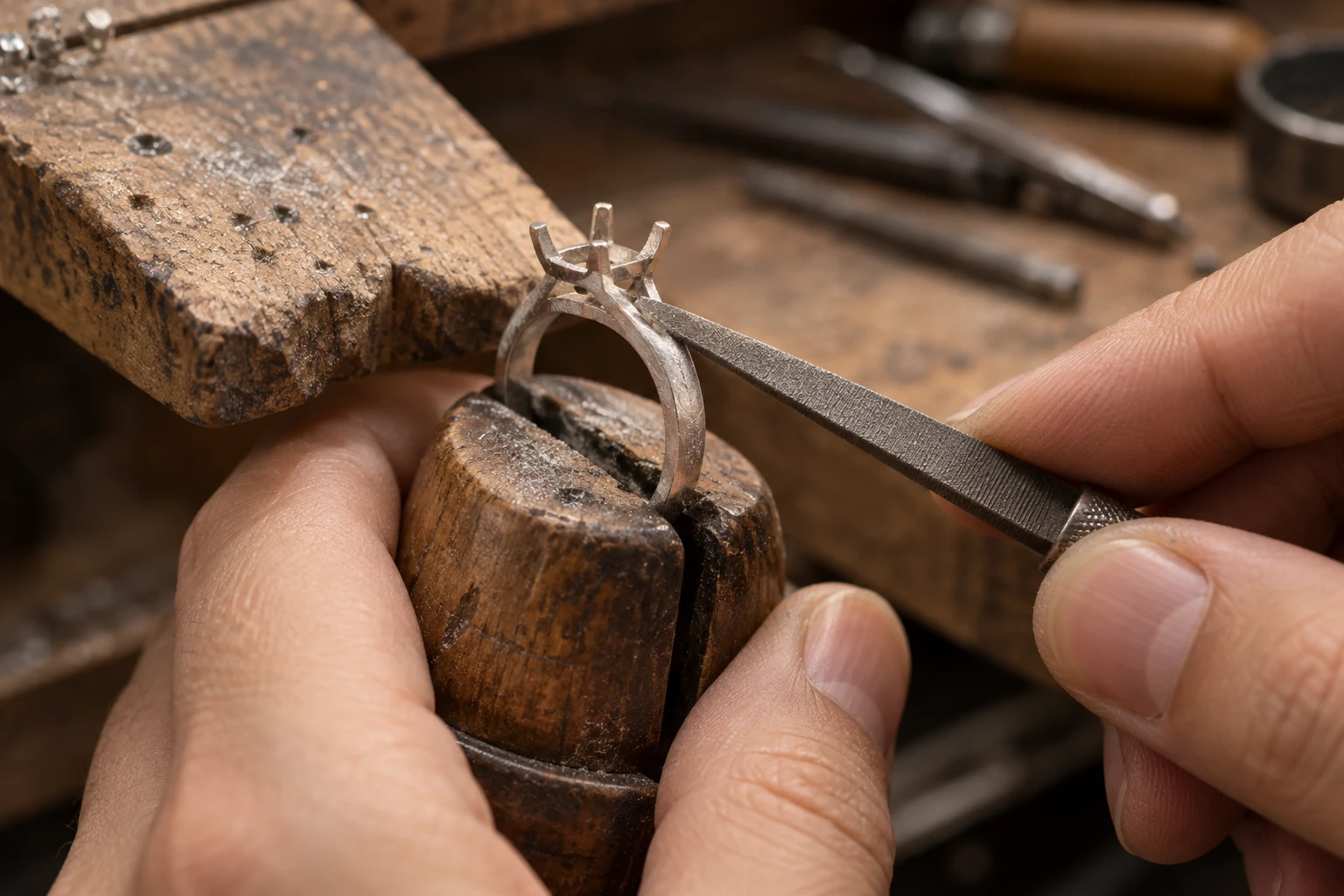
On the wax route, complete support removal and pattern inspection before handing the patterns over for casting. The resulting metal blanks still need gate removal, cleaning, fettling and the specified machining or surface treatment. Printed patterns do not automatically remove these downstream tasks.
Ransom & Randolph’s jewelry casting process uses an invested wax tree to explain mold preparation, wax removal, pouring and subsequent finishing. Jewelry investing and industrial ceramic shell building follow different procedures; prepare for the relevant materials and casting system.
Distinguish the two removal stages. Removing printing supports preserves a complete wax pattern. Dewaxing after the mold is formed removes the pattern itself to leave a cavity for metal. The operations occur at different stages and serve different purposes.
| Comparison point | Direct metal printing with LPBF | Printed wax patterns followed by casting |
|---|---|---|
| Print-stage output | Metal part and associated supports | Wax pattern and support material |
| Material control | Powder, process parameters and post-processing condition | Wax, plus the downstream alloy and casting conditions |
| Process interfaces | Build preparation and metal post-processing | Pattern handover, tree assembly, mold preparation and pouring |
| Common preparation issues | Orientation, supports, powder removal and machining | Cleaning, gating, cores and machining allowances |
| Final inspection | Dimensions, material and properties required for the application | Dimensions, material and properties required for the application |
This table identifies the work involved. It does not provide a universal ranking: equipment, materials and supplier capabilities can also differ within each category.
5. Compare cost and lead time at the same acceptance stage
If one quote covers a finished metal part and the other only a wax model, the amounts cannot directly determine the better manufacturing route. First agree whether the comparison ends at a metal blank or a fully machined part, then include the corresponding operations.
For blanks, specify the condition of gates or supports, surfaces awaiting machining and included inspections. For finished parts, add surface, critical dimension, setting or functional requirements, and define packaging and delivery scope.
Lead time must also start from the same input status. For example, use approved files and complete material requirements as the starting point, then check preparation, queueing, manufacture, post-processing, inspection and transport for each route. Comparing LPBF build time with wax printer operating time compares two different tasks.
Separate one-time qualification from repeat production. Itemize material or functional testing needed for the first batch. For repeat orders, explain which validation can be reused and which must be repeated after a revision.
Neither “no casting step” nor “cheaper wax” alone determines the final cost. Existing process resources, finishing difficulty, quality requirements and accepted delivery quantities all contribute to the actual expense.
Ask both suppliers to itemize the same scope: design and process preparation, materials and manufacture, post-processing, inspection, and delivery. List one-time validation separately, then divide the total for the agreed scope by the accepted quantity to compare cost per conforming part. For precious metals, also clarify material ownership, recovery and loss accounting so that quote items are not overlooked.
If further validation is needed, select the same approved product revision and critical areas. Record manufacturing adjustments, completion status and inspection results for each route. Identify any change in geometry or delivery scope. This compares the proposals suppliers can actually deliver, rather than nominally identical samples with different requirements.
6. Give both suppliers the same product requirements
Keep product requirements consistent while allowing each supplier to propose its manufacturing plan. This supports a like-for-like comparison and lets suppliers explain necessary process differences.
Use existing resources to decide where to start:
- If casting and finishing processes already suit the target alloy and the aim is mainly to change designs or obtain patterns differently, first assess how printed wax patterns could enter that workflow.
- If direct metal manufacture is intended to achieve a particular structure, ask an LPBF supplier to review material, depowdering, supports and machining access before evaluating the complete delivery proposal.
- If both routes have viable proposals, compare samples made to the same approved product revision. Record manufacturing adjustments and final inspection results before selecting a production route.
| Input | What to specify |
|---|---|
| End use | Wearability, assembly or function, and service conditions |
| Material requirements | Alloy, material documentation and required delivery condition |
| Geometry and revision | CAD revision, critical dimensions, holes, cavities and fine connections |
| Post-processing | Surface, machining, stone setting or assembly requirements |
| Inspection | Dimensions, appearance, material and required functional checks |
| Quantity and variation | First batches, repeat orders, sizes and possible revisions |
| Resources and timing | Existing casting or machining capability and latest handover dates |
Each supplier should explain geometric suitability, required changes, the operations it will undertake and how delivery conformity will be demonstrated. Projects needing functional validation should include the relevant tests and material records.
When switching routes, reconfirm manufacturing adjustments and final acceptance even if the product CAD remains unchanged. Release decisions should follow inspection and validation, rather than appearance alone.
To assess the wax route, send Cprint 3D your CAD, critical features and downstream casting conditions to discuss pattern production and handover. Confirm final metal, machining and inspection requirements with the suppliers responsible for those operations.
Frequently asked questions
Does 3D-printed jewelry always mean directly printed metal?
It may mean direct metal manufacture or the production of casting patterns first. Ask what material the printer outputs and which operations follow to identify the actual route.
Can printed metal be worn or installed immediately?
It must be checked against the delivery requirements and receive the necessary post-processing. Printing is one manufacturing milestone; usability depends on material, dimensions, surface and validation for the intended use.
Can a printed wax pattern be cast in any metal?
The downstream casting system determines the final alloy. Check compatibility with the investment or shell, dewaxing and burnout, melting and pouring conditions. Pattern production capability does not replace the foundry’s confirmation of alloy and quality requirements.
Can the routes be compared by printing speed alone?
You can record each printing stage, but route selection should measure from complete approved inputs to the same delivery condition, including queueing, manufacture, post-processing and inspection. A completed wax model and a finished metal part are different milestones, so their completion times do not directly compare total order lead time.