

3D Printed Sand Molds and Cores for Casting
Cprint 3D enables foundries to produce complex sand molds and cores directly from approved casting data, reducing reliance on dedicated patterns and core boxes while supporting design changes and high-volume production.
DIGITAL SAND CASTING
Sand Molds and Cores, Produced Directly from Digital Data
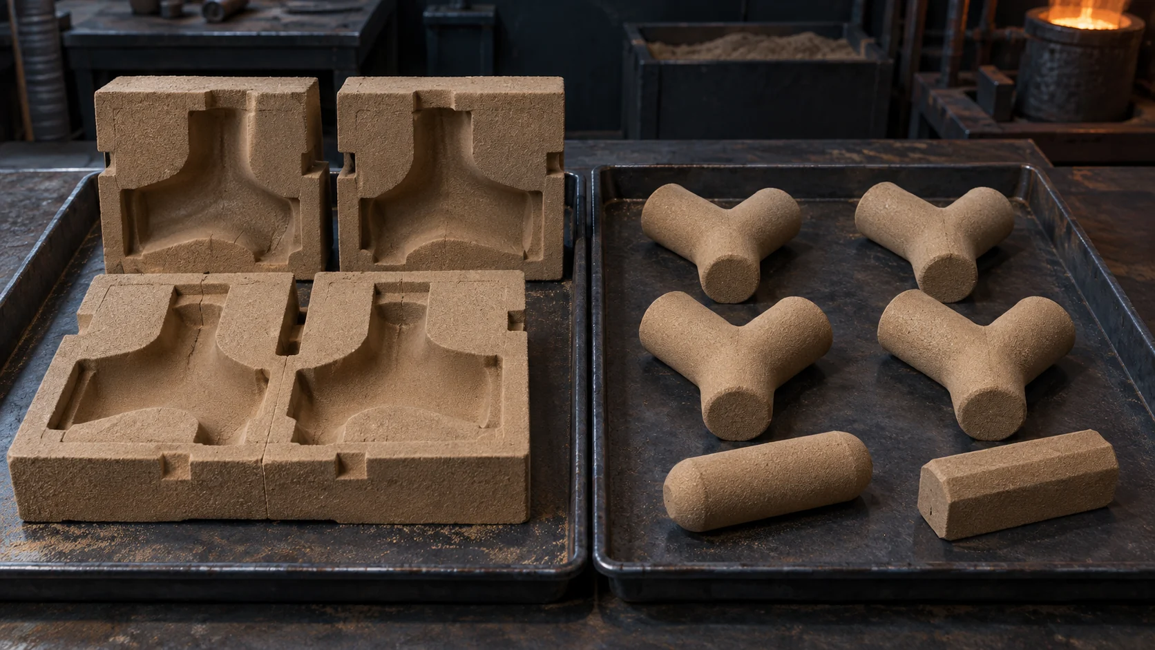
Choose a complete printed sand mold, a printed sand core, or a hybrid of printed components and conventional molding according to the casting geometry and production plan.

SAND MOLD · 01
3D Printed Sand Molds
Produce complete sand molds directly from approved casting data with less reliance on dedicated physical patterns. Digital files can be updated and reused across production runs, supporting complex mold geometry, mixed orders, and high-volume manufacturing.
SAND CORE · 02
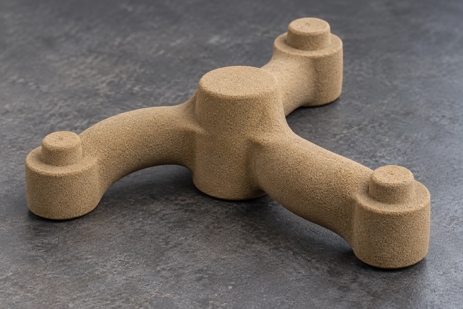
3D Printed Sand Cores
Create cores for internal cavities and flow passages that are difficult to make with conventional core boxes or multi-piece assemblies. Printed cores can be used with digitally produced molds or integrated into conventional molding lines for repeat and high-volume casting production.
The sand mold forms the casting’s external surfaces; the sand core forms internal cavities and passages. Both are casting intermediates and must be matched to the foundry’s material, assembly, and pouring conditions.
APPLICATION FIT
Casting Tasks for 3D-Printed Sand Molds and Cores
Digital sand production is most valuable when sustained demand is combined with complex geometry, frequent design changes, or conventional core-making constraints.
01 · PRODUCTION SCALE
Multi-Variant, High-Volume Production
Arrange different approved molds and cores within planned production builds, then reuse controlled digital data across repeat orders. Output and economics should be evaluated against part size, nesting, material systems, shift plans, and accepted casting requirements.

02 · CORE CONSOLIDATION
Consolidated Complex Cores
Where casting and core-removal conditions allow, several conventionally manufactured core sections can be redesigned as fewer integrated printed cores. This can reduce assembly interfaces while preserving the positioning, venting, handling, and shakeout requirements of the foundry process.

03 · INTERNAL GEOMETRY
Internal Passages and Complex Cavities
Produce curved, branching, or intersecting passages that are difficult to manufacture with conventional core boxes and pull directions. Channel size, loose-sand removal, gas flow, coating, and casting cleanout still require project-specific validation.

04 · REPEAT PRODUCTION
Design Changes and Repeat Production
Revise approved production data without rebuilding a dedicated physical pattern or core box for every change. Controlled files can support repeat orders and product variants, while each geometry or process change remains subject to engineering review.
PRODUCTION ADVANTAGES
Why Foundries Adopt Digital Sand Production
Digital sand production adds scalable mold and core capacity while allowing foundries to combine printed components with established molding and casting operations.
01 · PRODUCTION PLANNING
Plan for High-Volume Output
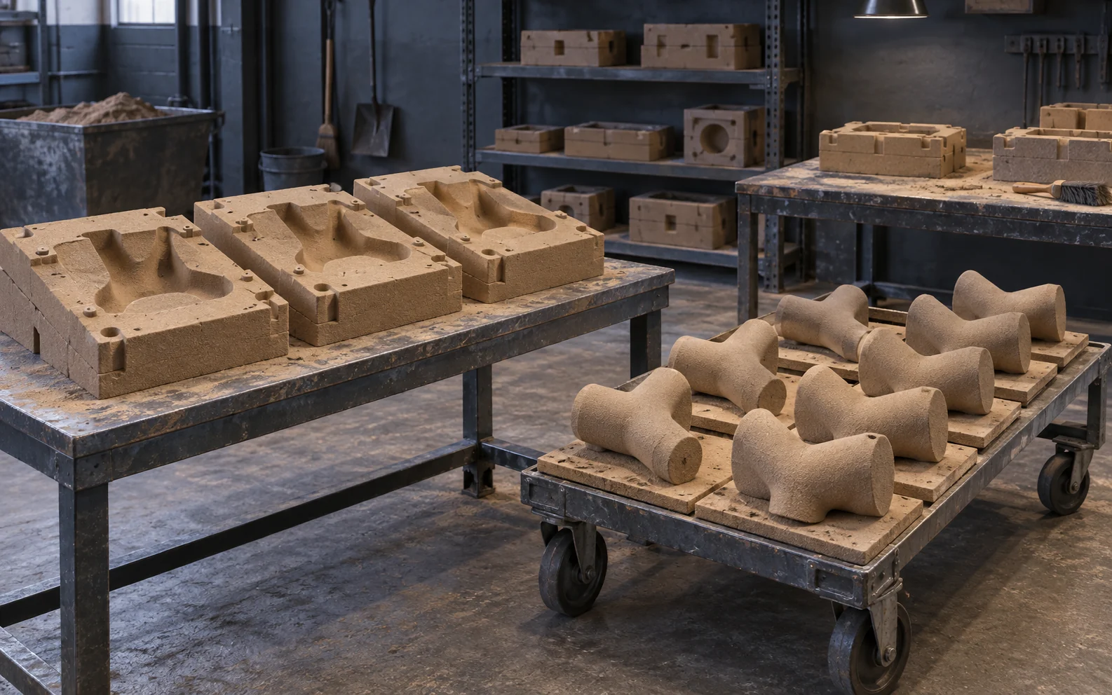
Controlled build layouts, repeatable production data, and coordinated build-box turnover allow molds and cores to be organized around ongoing batch demand. Practical output still depends on part size, nesting density, sand removal, inspection, shift patterns, and downstream casting capacity.
02 · MIXED ORDERS
Run Mixed Orders with Greater Flexibility
Different approved mold and core geometries can share a production schedule without requiring a separate physical pattern or core box for every item. Jobs can be grouped around delivery priorities, compatible materials, and downstream capacity.
03 · HYBRID MOLDING
Combine Printed and Conventional Molding
Print the complex internal core while retaining an efficient conventional external mold. This hybrid route concentrates digital production on the most difficult geometry while preserving mature molding capacity for the rest of the casting.
04 · FOUNDRY INTEGRATION
Keep Established Casting Operations in Place
After cleaning and validation, printed molds and cores can enter established coating, assembly, pouring, shakeout, finishing, and inspection routes. Digital production changes how the sand components are made; it does not require every downstream process to be replaced.

VERIFIED EVIDENCE
Foundry Evidence and Latest Sand 3D Printing Guides
Review a documented foundry operation and the latest practical guidance for sand mold, core, material, workflow, and production decisions.
 FOUNDRY OPERATIONS CASE
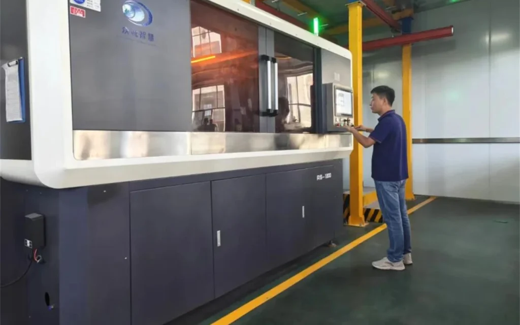
Long-Term Sand 3D Printer Operation at Xixia Exhaust Pipe
Authorized shop-floor records document a first-generation Cprint 3D system deployed in 2018 and a second-generation system added in 2025, with customer feedback covering long-term operation, maintenance, continuous production, and repeat purchase.
Operational evidence—not a mold-to-casting result comparison.
Read the Foundry Case
LATEST SAND 3D PRINTING GUIDES
View All Sand 3D Printing Guides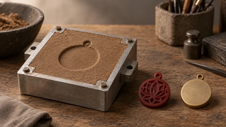 Can Jewelry Be Sand Cast? How It Differs from Lost Wax Casting
Read the Guide
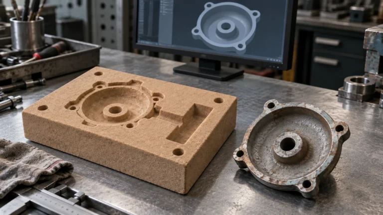 How Do You Remake Discontinued Parts Without Drawings? 3D Printing Revives Lost Manufacturing Know-How
Read the Guide
 From Coolant Passages to Complex Cavities: How Does 3D Sand Printing Help Make Engine Blocks?
Read the Guide
HAVE A QUESTION?
Frequently Asked Questions About 3D-Printed Sand Molds and Cores
Find practical answers about production scale, mold and core differences, foundry integration, complex geometry, and project evaluation.
A 3D-printed sand mold is produced by selectively binding foundry sand according to approved digital data. It forms the cavity used for metal pouring and can reduce reliance on a dedicated physical pattern. The printed mold is a casting intermediate, not the finished metal component.
The sand mold normally forms the casting’s external surfaces and contains the molten metal. A sand core creates internal holes, cavities, and flow passages. Both require validated sand, binder, strength, venting, coating, positioning, assembly, and post-casting removal conditions.
Yes, when part demand, mold and core size, build layout, material system, shift planning, cleaning, inspection, and downstream casting capacity support a stable production route. High volume is not defined by one universal part count; compare accepted molds, cores, and castings per shift with the complete conventional route.
Yes. This hybrid route keeps an efficient conventional external mold and prints only the difficult internal core. Core prints, shared datums, clearances, materials, coating, venting, handling strength, and revision control must be validated before repeat production.
Curved, branching, and intersecting passages can be suitable because the core does not have to be withdrawn from a physical core box. Feasibility still depends on passage size, loose-sand removal, cleaning openings, handling strength, venting, coating, alloy conditions, and removal of the core after pouring.
No. The solution produces sand molds and cores used in the casting process. Metal melting, mold assembly, pouring, cooling, shakeout, heat treatment, machining, finishing, and inspection remain part of the foundry’s complete production route.
Provide the casting CAD file or drawing, proposed mold or core data if available, overall dimensions and weight, alloy and pouring conditions, expected quantity and delivery cadence, critical tolerances and surfaces, current sand and binder system, existing tooling, shift targets, and the production problem to be solved.
DISCUSS YOUR PROJECT
Discuss Your Sand Mold and Core Project
Share the project information you already have. Our application team can review the casting geometry, sand mold or core requirements, planned production volume, foundry process, and existing tooling to define the next practical evaluation step.
PROJECT INFORMATION TO INCLUDE
- CAD file or technical drawing
- Casting dimensions and target weight
- Sand mold, sand core, and assembly requirements
- Target alloy and casting process
- Expected quantity, production frequency, and shift target
- Existing pattern, core-box, and tooling status
- Critical tolerances, surface, and inspection requirements
- Target schedule and current production challenge
You do not need a complete technical package to begin. For confidential projects, send a non-sensitive summary first and tell us before sharing restricted files. Accepted upload formats and limits are shown in the form.